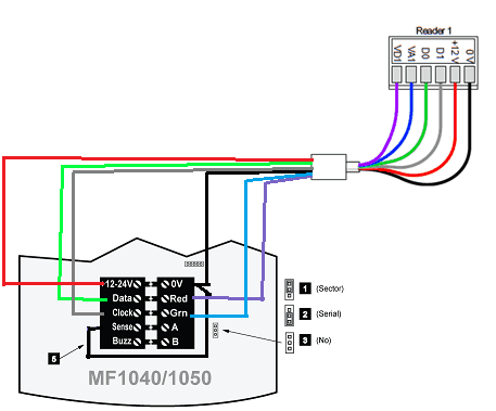
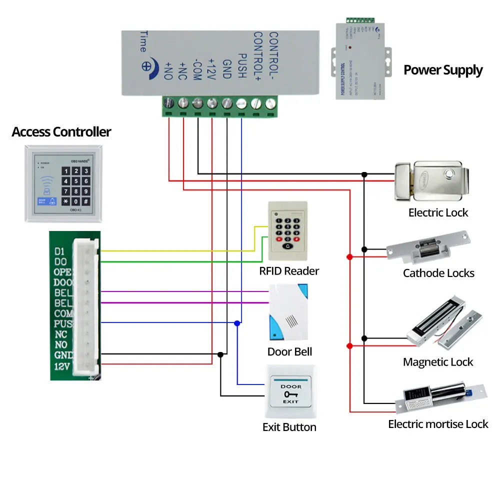
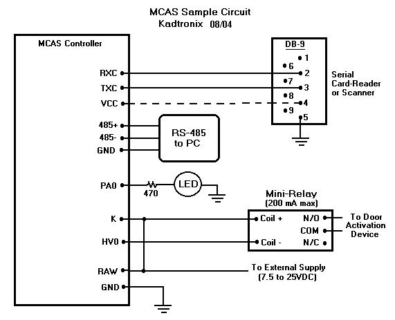
41 access control card reader wiring diagram
The following common wiring diagrams are available: One Single Door with Panic Bar. Electric Latch Retraction, with Auto Operator ... Access control with electric strike and LCN 4600 automatic operator; ... can automatic door opener work with and card reader strike
The diagram below shows the general wiring layout for a Net2 plus ACU. Not all of the equipment shown needs to be installed on every door. For example, when using Timesheet it is only necessary to install a reader and the data connection. The selection of ACU type and their method of connection to the Net2 server PC (TCP/IP, RS485,
Basic installation of access control system full electronics project electric rfid id password safty entry door lock magnetic set panel hcrfid0002 forum hobbycomponents com how to wire your kintronics cables and wiring diagram kisi 12 67 free or cheap shipping card reader stand alone em c at m fasttech mobile security proximity 10 keys alexnld dc12v 3a switch… Read More »
Access control card reader wiring diagram
Oct 10, 2021 · Variety of access control card reader wiring diagram. A wiring diagram is a streamlined traditional photographic representation of an electric circuit. It shows the components of the circuit as streamlined forms, as well as the power and signal connections in between the gadgets. A wiring diagram normally offers details regarding the relative position as well as setup of gadgets and also terminals on the gadgets, to assist in structure or servicing the device.
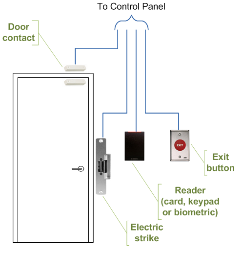
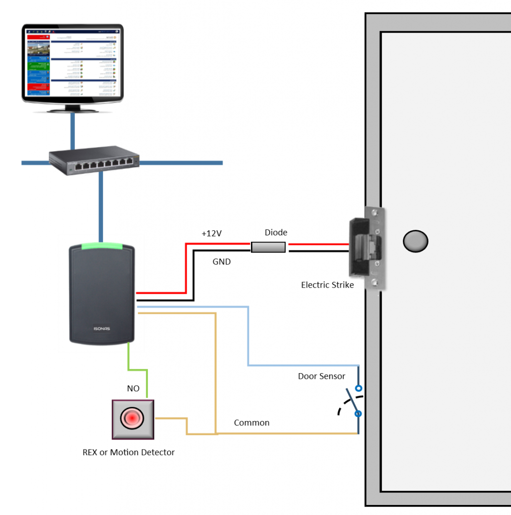
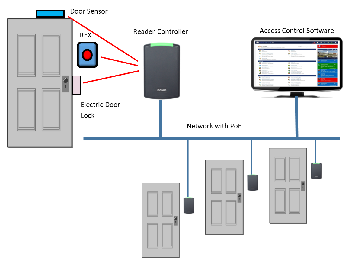
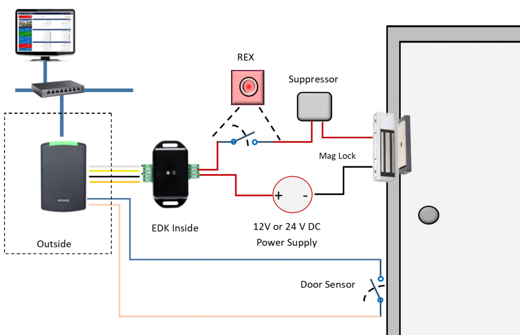
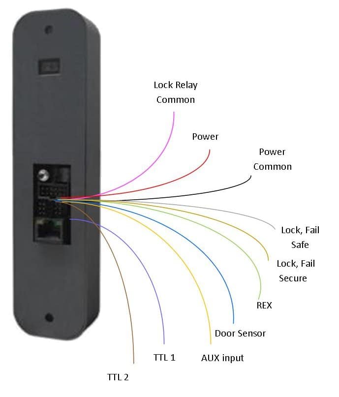
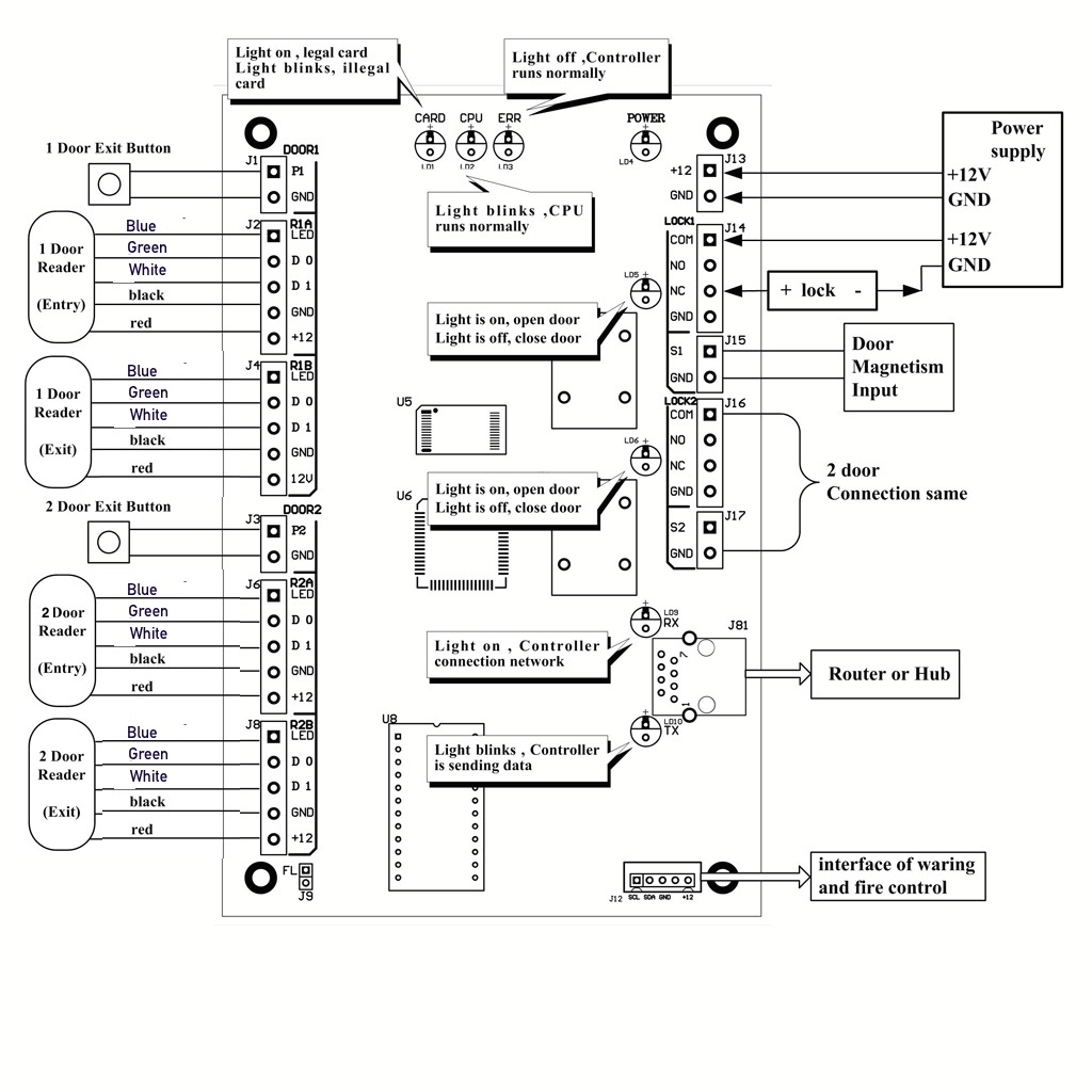
Access Control Diagram The reader-controllers attach to the network and use PoE. They include a pigtail of wire that connect to the electric lock, the REX button, door sensors, and motions detectors. There are several configurations available, and they all use special software for access control management.
Wiring Diagram Proximity Card Radio Frequency Identification Hid Global Reader Png Clipart Access Badge Angle. Basic Installation Of Access Control System Full Electronics Project. Avea Decorative Rfid Proximity Card Reader Audit Trail Rs232 Connection. Prxtsec125khz 125 Khz Proximity Card Reader User Manual Integrated Control Technology.
Access control card reader wiring diagram.
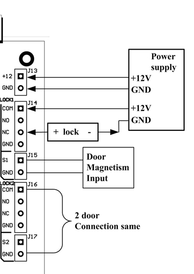
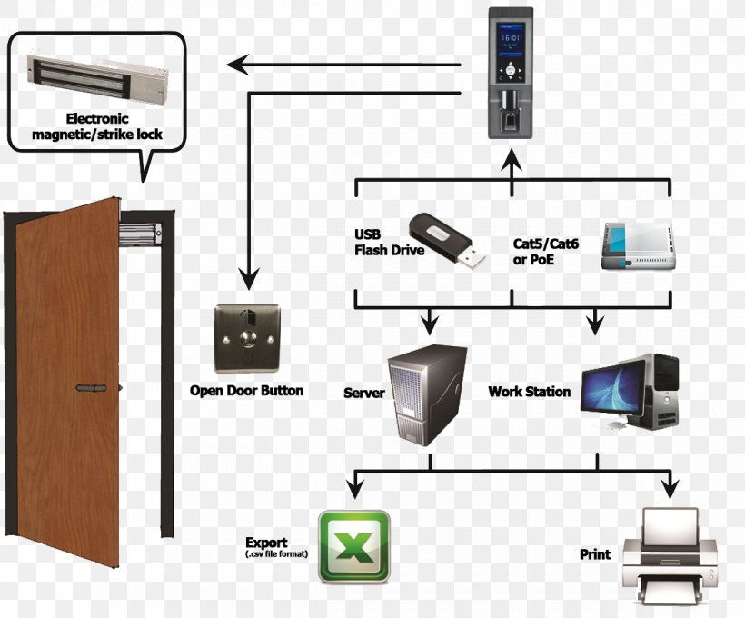
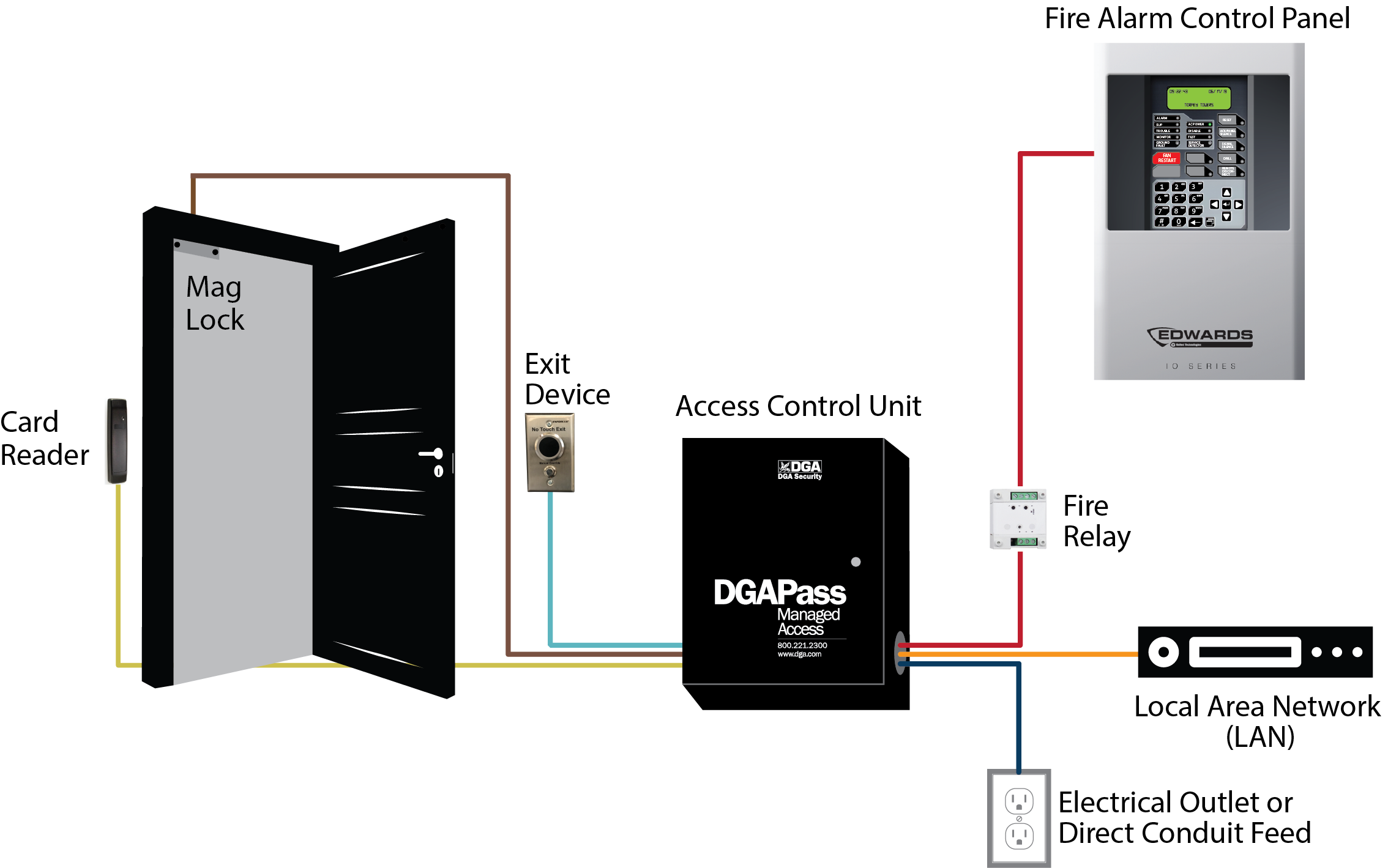
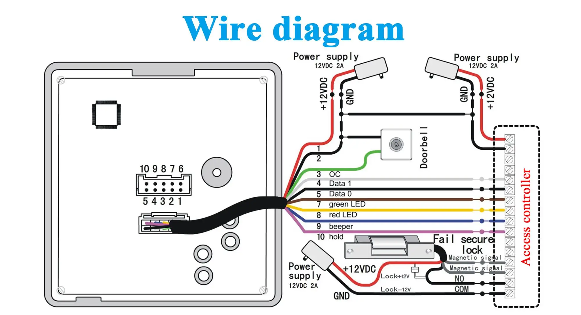
A basic wiring diagram of an access control system The ACU functions as the traffic controller as well as the primary power source for all the devices connected to the access control system. When a valid credential is presented to a reader located at a door, the ACU temporarily interrupts the power supply to that door's locking method (which ...
Access Control Systems An access control system is an integration of hardware, software, and management tools that electronically monitor and control access through door, gates, elevators, and many other entry points. Access control systems are found virtually everywhere. They can be found in Hotels, Hospitals, Airports, Banks,
Jan 01, 2020 · Access Control Card Reader Wiring Diagram – wiring diagram is a simplified gratifying pictorial representation of an electrical circuit. It shows the components of the circuit as simplified shapes, and the gift and signal contacts between the devices.
an access device (card reader) in the elevator car to enable building residents to activate the floor buttons according to the security level assigned to them. 1.1 General Information . Up to eight (8) elevators may be controlled by up to eight (8) DoorKing Access Control Systems (1833, 1835, 1837, 1838) at four (4) entrances.
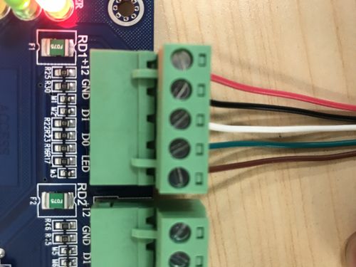
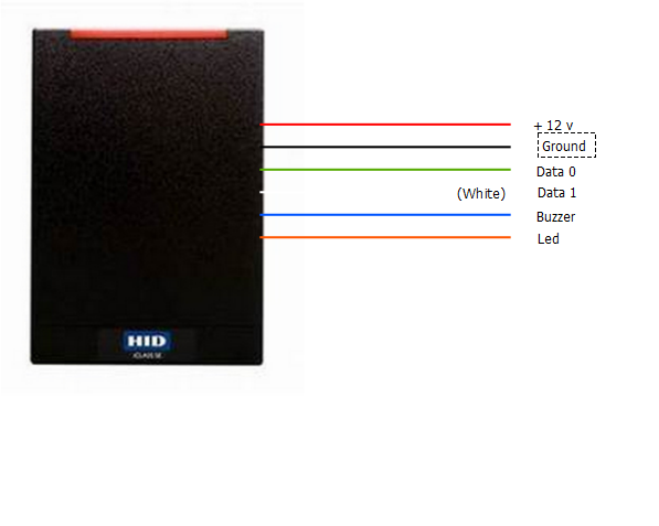
Below are the wiring diagram to connect the card reader using Wiegand Protocol: The Operation of LED is controlled by the Access Controller, the LED operation may vary depending on the Access Controller software. The normal behavior, the LED on card reader will turn Green to indicate that card is read and privileged. 1.
PROXIMITY CARD ACCESS CONTROL SYSTEMS PART 1 - GENERAL Detailed wiring diagram for the connection of relays as applied in the interfacing Provide and install a Model HID Prox Pro or equal card reader at each elevator in conjunction and with the assistance of the elevator contractor. 3. Connect the Reader and Host together according to the ...
Zkteco wiring diagram. 5please connect the gnd before all the other wiring especially under the environment with much electrostatic. Diagram of system construction. Be advised that wiring the device while power is on may cause damage to the terminal. Power wiring diagram without backup battery with backup battery switching power supply ground ...
The following diagram shows the wire types and max lengths that are recommended for use with the Verkada AC41. We recommend using one twisted pair for - (ground) and + (power) and one twisted pair for the data (D0/D1, in the case of a Wiegand reader, or A/B, in the case of a Verkada Reader). Access control combo/trunk cabling may be used, as ...
Description. This article is to show how to wire Dahua Card Reader to Dahua Access Controller using RS-485 Protocol. An RS485 bus is capable of covering up to 1000m end to end, using twisted-pair cables. An RS485 bus can offer good immunity to electrical noise, making it ideal for interconnecting components around buildings.
Table of Contents 8 — revision 1 BAS-1320 Dual Reader Interface Module .....255 45. Overview of the BAS-1320 .....257
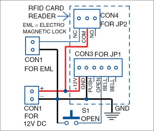
It includes 3- and 6-pin connectors along with 3- and 6-wire cables to connect the access control device. The complete wiring diagram for the project is shown in Fig. 2. Fig. 1: Block diagram of author's prototype Fig. 2: Wiring diagram of access control system Relay connections. Let us go through the relay concept before the actual installation.
- Card Reader Wire: Pulled to single gang box at the card reader location: A (3) pair 22-gauge shielded stranded gauge wire shall be used for the door reader and pulled through a ¾ inch flex conduit from the junction box to a single gang junction box in the area designated for mounting of the card reader. - Handicap Door Controller Cable:
Each reader port can accommodate a reader that utilizes TTL (D1/D0, Clock/Data), F/2F (standard or supervised) or 2-wire RS-485 device signaling (OSDP reader for example) and also provides tri-state LED control, and buzzer control (one wire LED mode only). Four Form-C relay outputs may be used for door strike control or alarm signaling.
Access Control Composite Cables | PB00093 | V3_ECOS_BDC_0617_A_AG Belden Lock Power Part Number Flame Rating (Gray) Card Reader (Orange) Door Contact (White) Request Exit/Spare (Blue or Yellow) Assembly Standard 558AFS CMR 4C, 18 AWG, Shielded 3 Pr, 22 AWG, OA Shield 2C, 22 AWG, Shielded 4C, 22 AWG, Shielded (Blue) 658AFS CMP Banana Peel ...
Collection of access control card reader wiring diagram. A wiring diagram is a streamlined standard pictorial representation of an electrical circuit. It reveals the components of the circuit as streamlined shapes, as well as the power as well as signal connections in between the devices. A wiring diagram usually provides information about the loved one placement and also setup of gadgets and also terminals on the gadgets, in order to help in building or servicing the gadget.
I will use our DX Series 2 Door Access control Board , a Proximity Card Reader , an electronic door strike (ACDS-DX1500SE), 22-8 wire and a power supply with at least 3 or 5 amps. In this article I will cover the steps to wire the electronic door strike and access control reader to the board and test the system.
Oct 29, 2020 · Collection of access control card reader wiring diagram. A wiring diagram is a streamlined standard pictorial depiction of an electric circuit. It reveals the components of the circuit as simplified forms, and the power as well as signal connections between the devices.
Power Wiring Diagram ..... 11 Without Backup Battery ... InBio Pro Series Access Control Panels INSTALLATION GUIDE InBio Pro Series Access Control Panels INSTALLATION GUIDE ... Wiegand Card Reader ZK4500 Enrollment reader RS485 Convertor RS485 Fingerprint Reader Prox Card CR20E Card Enroller K2 Exit Button InBio Pro Cabinet
Access_Control_Proximity_Setup(20160502).doc Page 7 of 21 Rev. 20160502 V. Additional Access Control Configurations Electric Door Strike (Normally Open Circuit) MagLock (Normally Closed Circuit) VI. Where to Place the Hardware The Proximity Card Reader or Wiegand Keypad should be mounted near the door. It does not need to
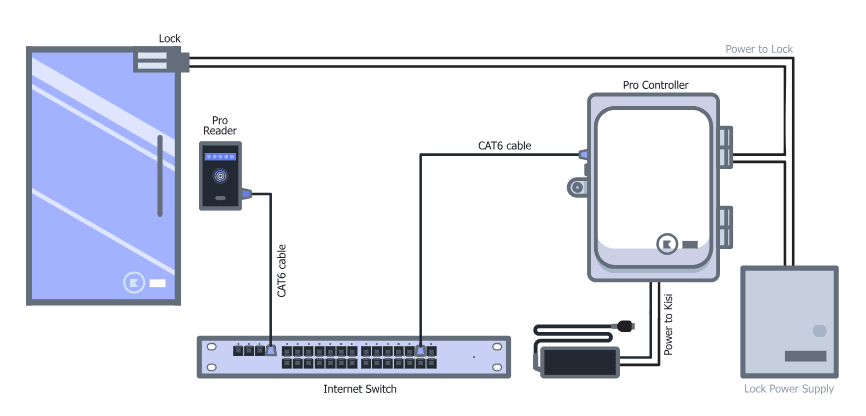
Door Access Control System Wiring Diagram. Below is a visual representation of how to wire your access control system: CAT6 cables connect readers and controllers to the internet switch. Power is supplied to the door lock and the Kisi Pro Controller. Kisi wiring diagram.
Apr 30, 2018 · Access Control Card Reader Wiring Diagram Download. July 30, 2018. April 30, 2018 by faceitsalon. Assortment of access control card reader wiring diagram it is possible to download at no cost. Please download these access control card reader wiring diagram by using the download button, or right click on selected image, then use Save Image menu. Wiring diagrams help technicians to determine the way the controls are wired to the system.
What is the wiring diagram for OSDP? If you're interested in having a more in-depth look at how it works, take a look at this OSDP protocol example diagram, which gives an insight into how to use it with existing Wiegand devices. This includes how to connect both a Peripheral Device (PD) or Access Control Unit (ACU), or both.
Power Wiring Diagram ..... 11 Without Backup Battery ... Wiegand Card Reader ZK4500 Enrollment reader RS485 Fingerprint Reader Prox Card CR20E Card Enroller ... InBio Pro Series Access Control Panels INSTALLATION GUIDE › 192.168.1.201 ...
May 01, 2018 · access control card reader wiring diagram – Just What’s Wiring Diagram? A wiring diagram is a sort of schematic which utilizes abstract pictorial icons to reveal all the affiliations of elements in a system.

Hfeng fingerprint door locks system rfid access control reader biometric electronic door opener with smart key cards wg26 sd card
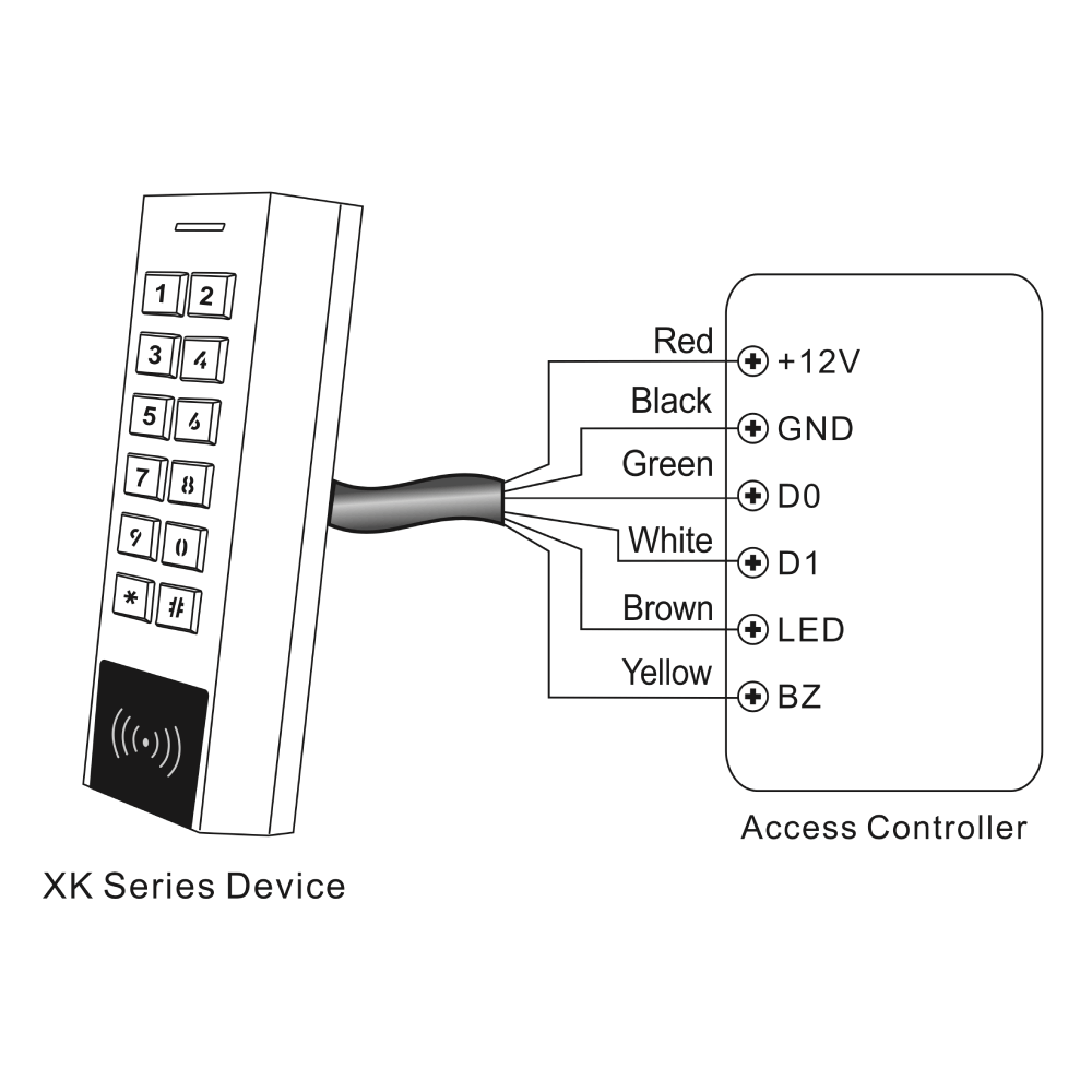
Fhd-kb-xk2 inteliprox new slim standalone keypad access control system and wiegand card reader – pin, 125khz em card and hid card











0 Response to "41 access control card reader wiring diagram"
Post a Comment