40 draw the shear diagram for the beam. 7.85.jpg
A uniform beam has a mass of 18 kg and rests on two surfaces at points A and B. Determine the maximum distance x to which the girl can slowly walk up the beam before it begins to slip. The girl has a mass of 50 kg and walks up the beam with a constant velocity. A. x=0.678 m B. x=0.712 m C. x=0.508 m D. x=1.005 m
diagrams and the equations of statics. 25. Due to the load transfer process in truss systems, no discontinuity will exist in the member force influence line diagrams. Furthermore, since we are restricting our attention to . statically determinate struc-tures, the . influence line diagrams will be piecewise linear. 26. Example Truss Structure
1. Analyse the continuous beam given in figure by slope deflection method and draw the B.M.D 2. Analyze the frame given in figure by slope deflection method and draw the B.M.D 3.Using slope deflection method, determine slope at B and C for the beam shown in figure below. EI is constant. Draw free body diagram of BC. 4.
Draw the shear diagram for the beam. 7.85.jpg
Classify the beams shown in Figure 3.1 through Figure 3.5 as stable, determinate, or indeterminate, and state the degree of indeterminacy where necessary.. Fig. 3.1. Beam. Solution. First, draw the free-body diagram of each beam. To determine the classification, apply equation 3.3 or equation 3.4.. Using equation 3.3, r = 7, m = 2, c = 0, j = 3. Applying the equation leads to 3(2) + 7 > 3(3 ...
Example 4.7 For the beam loaded as shown in Fig. E4.7, compute the moment of area of the M diagrams between the reactions about both the left and the right reaction. (Hint: Draw the moment diagram by parts from right to left.) Figure E4.7
Example: Analyze two span continuous beam ABC by slope deflection method. Then draw Bending moment & Shear force diagram. Take EI constant Solution: Fixed end moments are: 41.67KNM 12 20 5 12 wL F 41.67KNM 12 20 5 12 wL F 88.89KNM 6 100 4 2 L Wa b F 44.44KNM 6 100 4 2 L Wab F 2 2 CB 2 2 BC 2 2 2 2 BA 2 2 2 2 AB
Draw the shear diagram for the beam. 7.85.jpg.
3 KN / m YOKN 5 KN 8 m, EI B 3 m 3 m calculating distribution factor. 3 m > Joint Members Member stiffness Joint stiffness Distribution B BA 4EJ factor BC 8 3 EI 1/ 2 ET 1/2 SB Now, calculating fixed end momements, 3 kal A PA = M 8 20 12 May IbKam 2 3x 82 12 = 16 KN -M JOKN 3 m MOBC Z MRCB PL 8 MEBC FCB = 10x 6 = 7. 5 kN- m * 15 KN- m Moment in ...
Equations of Equilibrium: Referring to the free-body diagram of the beam shown in Fig. a, a Shear and Moment Diagram: As shown in Figs. b and c. A y = 1000 lb +c©F y = 0; A y + 1000 - 400 - 200(6) - 400 = 0 B y = 1000 lb +©M B y(6) + 400(3) - 200(6)(3) - 400(9) = 0 A = 0; 6-39. Draw the shear and moment diagrams for the double overhanging ...
Draw the shear and moment diagrams for the beam, and determine the shear and moment throughout the beam as functions of x. 2 kip/ft 8 kip x 10 kip 40 kip ft A 30 kip ft B 5 ft 5 ft 2 kip/ft 5 ft 6-19. Draw the shear and moment diagrams for the beam. 06 Solutions 46060_Part1 5/27/10 3:51 PM Page 338
Draw B.M and S.F diagrams. A fixed beam AB of length 6m carries two point loads of 30 kN each at a distance of 2m from the both ends. Determine the fixed end moments and draw the B.M diagram. Find the fixing moments and support reactions of a fixed beam AB of length 6m, carrying a uniformly distributed load of 4kN/m over the left half of the span.
Answer to Fundamental Problem 6.7 Part A Draw the shear diagram for the beam. Part B Draw the moment diagram for the beam....
BEAM ANALYSIS USING THE STIFFNESS METHOD. 2 Slope Œ Deflection Equations settlement = ... ŁKnown degrees of freedom D4, D5, D6, D7, D8 and D9
Answer to 7.78 Draw the shear and moment diagram for the beam.
Section. 7.1 Internal Loadings Developed In Structural Members 7.2 Shear And Moment Equations And Diagrams 7.3 Relations Between Distributed Load, Shear, And Moment 7.4 Cables. Problem 7FP. Problem 8FP. Problem 9FP. Problem 10FP. Problem 11FP. Problem 12FP. Problem 45P.
Draw the shear force and bending moment diagram for the beam. Draw the shear force and bending moment diagram for a simply supported beam of length 9m and carrying a uniformly distributed load 10KN/m for a distance of 6m from the left end. Draw S.F and B.M diagram for a simply supported beam ...
7-83. Draw the shear and moment diagrams for the shaft. The support at A is a journal bearing and at B it is a thrust... 7-84. Draw the shear and moment diagrams for the beam.... 7-85. Draw the shear and moment diagrams for the beam. ... 7-86. Draw the shear and moment diagrams for the beam.... 7-87. Draw the shear and moment diagrams for ...
Answer to Problem 7.79 Part A Draw the shear diagram for the beam. Click on "add vertical line off" to add discontinuity lines. Th...
Draw the shear and moment diagra ms for the lathe 7_74. Draw the shear and moment diagrams for the beam.shaft if il iS5ubjected to the loadssho\"·n.The bearing al;\ isa journal bearing, and 8 is a thrust bearing. ... Draw the shcura nd moment diagrnm§ for the beam. 7-37. Draw the shear and moment diugranls for the shafl. ... l' rob.7-88 Proh.7-85
Answer to draw the shear and moment diagrams for the beam. Can you also finf=d values of x, V and M...
7-85. Draw the shear and moment diagrams for the beam. ... 7-86. Draw the shear and moment diagrams for the beam.... 7-87. Draw the shear and moment diagrams for the beam.... 7-88. Draw the shear and moment diagrams for the beam.... 7-89. The shaft is supported by a smooth thrust bearing at A and a smooth journal bearing at B. Draw the ...
Answer to Draw the shear and moment diagrams for the beam....
Analysis of Simple Diaphragm and Shear Wall Systems Problems Analysis of Statically Determinate Structures. 2 ... Example 2-7 Determine the reactions on the beam shown. Assume A is a pin and the support at B is a roller (smooth surface). A 3 m 4 m 2 m 7 kN/m B. 36
Answer to Draw the shear diagram for the beam. Follow the sign convention. (Figure 1) Draw the moment diagram for the beam. Follo...
6—25. Draw the shear and moment diagrams for the beam- The two segments are joined together at B. 8 kip 3 kip,ft 5 ft *6—20. Draw the shear and moment diagrams for the beam, and determine the shear and moment throughout the beam 10 kip 2 kip/ft g Kip 8 kip 40 kip.ft as functions of x. Support Reactions: As shown on FBD. Shear and Moment ...
September 26, 2020 - Shear force and bending moment diagrams bending moment diagrams sfd bmd 1 draw the shear and moment diagrams moment diagram graphical method 1 draw the shear and moment diagramsSolved 7 48 Draw...
Answer to Part A> Draw the shear diagram for the beam. Follow the sign convention. (Figure 1) Part B> Draw the moment diagram for ...
Shear and moment diagrams and formulas are excerpted from the Western Woods Use Book, 4th edition, and are provided herein as a courtesy of Western Wood Products Association. Introduction Notations Relative to "Shear and Moment Diagrams" E = modulus of elasticity, psi I = moment of inertia, in.4 L = span length of the bending member, ft.
Problem 7.53 Part A Draw the shear diagram for the beam. Click on "add discontinuity" to add discontinuity lines. Then click on "add segment" button to add functions between the lines. add vertical line off add segment 0 lb/ft 200 lb ft 20 ft 0 ft Vlb 400 300 200 100 x,ft 30 10 100 Submit My ...
Solution for 7.80 & 7.85 For the beam and loading shown: a) Draw shear force and bending moment diagrams, b) Determine the maximum absolute values of the shear…
*7—56. Draw the shear and moment diagrams for the cantilevered beam. 300 1b - diagram of the beam's left through an arbitrary shown in fig. b will be to write the and mcnnent quations. The inœnsity the triangldar útributed load at of sectioning is — = 3333r Referring Fig. b , o V = {-300- 1b — +3001-0 The shear and diagrams shown in ...
For the beam and loading shown, (a) draw the shear and bending-moment diagrams, (b) determine the maximum absolute values of the shear and bending moment.217 pages
Answer to Problem 7.75 Draw the shear diagram for the beam. Draw the moment diagram for the beam....
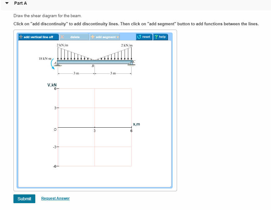
17 Dec 2020 — Draw the moment diagram for the beam. add vertical line off delete + add segment â–¼ 5 reset ? help 2 kN/m 2 kN/m 18 kN m 3 ...
Answer to Problem 7.55 Draw the shear diagram for the beam. Click on "add vertical line off to add discontinuity lines. Then click...
Q: Level III: AC/Waves: (a) In a few sentences and using a sketch, state the Lorentz's Force Law ... The shear stress developed in the bolts at joint B c.
Answer to Problem 7.64 Part A Draw the shear diagram for the beam. Follow the sign convention. Part B Draw the moment diagram for ...
10 Feb 2020 — [20 Points) Sketch free-body diagrams for sphere A, sphere B, and the container, ... Determine the plots of the shear and moment diagrams.
Draw the shear and moment diagrams for the beam. Follow the sign convention. no title provided. Expert Answer.
Answer to 7.76 Draw the shear diagram for the beam. Draw the moment diagram for the beam....
Draw the shear and moment diagrams for the beam. 2 m 3 m 10 kN 8 kN 15 kNиm 6–6. Draw the shear and moment diagrams for the overhang beam. A B C 4 m 2 m 8 kN/m 6–7. Draw the shear and moment diagrams for the compound beam which is pin connected at B. 4 ft 6 kip 8 kip A C B 6 ft 4 ft 4 ft 06 Solutions 46060_Part1 5/27/10 3:51 PM Page 331 5.
• A beam is a structural member that is subjected primarily to transverse loads and negligible axial loads. • The transverse loads cause internal shear forces and bending moments in the beams as shown in Figure 1 below. w P V(x) M(x) x w P V(x) M(x) x Figure 1. Internal shear force and bending moment diagrams for transversely loaded beams.
Answer to Problem 7.56 Draw the shear diagram for the beam. Follow the sign convention. Draw the moment diagram for the beam. Foll...
Draw the moment diagram for the beam. Click on "add discontinuity" to add discontinuity lines. Then click on "add segment" button to add functions between the ...
Design of Beam (Examples and Tutorials) by Sharifah Maszura Syed Mohsin Tutorial 1: Simply supported beam Figure below shows a 5.5 m simply supported beam with size of 150 x 350 mm. The characteristic permanents and variable action acting on the beam are 3.0 kN/m (excluding self-weight and brick wall) and 3.5 kN/m. This beam has to support the ...
Draw the shear and moment diagrams for the 2000 lb 500 lb/ ft A B 9 ft 7–82. 9 ft Draw the shear and moment diagrams for the beam. w0 A B L 629 L 7 Solutions 44918 1/27/09 10:39 AM Page 630 © 2010 Pearson Education, Inc., Upper Saddle River, NJ.
Beams –SFD and BMD V = V 0 + (negative of area under the loading curve from x 0 to x) M = M 0 + (area under the shear diagram from x 0 to x) If there is no externally applied moment M 0 at x 0 = 0, total moment at any section equals the area under the shear diagram up to that section When V passes through zero and is a continuous
13 0q L 4 B = - v(L) = CCC (↓) 30 EI Example 9-5 an overhanging beam ABC with a concentrated load P applied at the end determine the equation of deflection curve and the deflection C at the end flexural rigidity of the beam is EI the shear forces in parts AB and BC are P
1 Answer to Problem 7.56 Draw the shear diagram for the beam. Follow the sign convention. Draw the moment diagram for the beam. Follow the sign convention. Figure 1 of 1 1.5 kN/m 2 m 4 m
Draw The Shear Diagram For The Beam.Transcribed Image Text from this Question. Now the shear force and bending moment diagrams can be plotte and are shown below To complete a shear force and bending moment diagram neatly you will need the following materials.
Dec 08, 2021 · The shear diagram of a beam is shown in the figure. Draw the shear diagram for the beam. 6.8.Place the appropriate function between the lines of discontinuity, ensuring the endpoints have the correct values. 1.6 2.4 (kn) 36 16 6. 6–9.
Draw the shear diagram for the beam. add vertical line off delete + add segment ? 5 reset ? help 2 kN/. Part B. Draw the moment diagram for the ...
Solved 7.88 Draw the shear and moment diagrams for the beam. | Chegg.com. Engineering. Civil Engineering. Civil Engineering questions and answers. 7.88 Draw the shear and moment diagrams for the beam.
This problem has been solved! See the answer. See the answer See the answer done loading. Problem 7.85. Part A) Draw the shear diagram for the beam. Follow the sign convention. Part B) Draw the moment diagram for the beam. Follow the sign convention. Show transcribed image text.

0 Response to "40 draw the shear diagram for the beam. 7.85.jpg"
Post a Comment