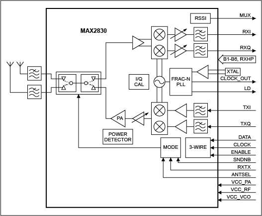
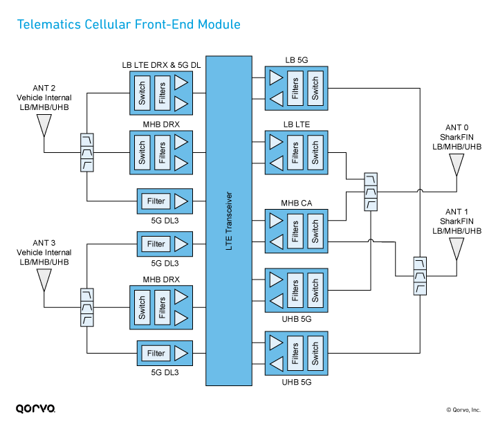
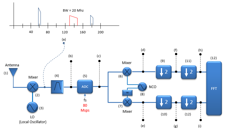
38 rf front end block diagram
Overview. NXP's RapidRF front-end designs for 5G infrastructure integrate a linear pre-driver, RF power amplifier, Rx LNA with T/R switch, a circulator and a bias controller in a compact footprint. They incorporate a coupler for DPD feedback and are to be used with digital pre-distortion.
Figure 3: Sub-Level Block Diagram Block 1: RF Front End A RF signal is input into the RF front end as shown in Figure 4. In lab, a signal generator produces the RF signal, but in application, an antenna would be used to receive the signal. The signal is amplified in a low-noise amplifier (LNA) to increase the power of the input signal.
Below is a non-exhaustive list of Qorvo RF front-end components and block diagrams for FDD and TDD small cell applications. Figure 6. Small cell FDD and TDD block diagrams. Table 1 . Learn to solve network congestion & efficiency with Small Cells. Download Now >

Rf front end block diagram
A Block Diagram of the GPS Orion receiver design appears in Figure 1. The GPS Orion receiver board com-prises the following components:- GP2015 ultra-miniature GPS RF front-end IC, including:-- RF input bandpass filter and +5V DC active antenna supply DW9255 GPS band-definition SAW filter, supplied by Dynex Semiconductor (www.dynexsemi.com).
Figure 1. SKY66420-11 Block Diagram . Description . The SKY66420-11 is a high-performance, highly integrated RF front-end module designed for high-power Industrial, Scientific, Medical (ISM) band applications operating in the 860 to 930 MHz frequency range. The SKY66420-11 is designed for ease of use and maximum
Figure-1 depicts internal diagram of 5G RF Front End components. RF Front End >> mainly refers to LNA and PA modules used between antenna and RF transceiver. As shown RF front end consists of PA (Power Amplifier), LNA (Low Noise Amplifier), Tx/Rx Switch, Wideband filter etc. It is connected between 5G Transceiver and antenna. Qorvo 5G RF Front End
Rf front end block diagram.
RF Front-End IF Block Back-End Baseband Demodulator ... RF Filter RF Power Amp Mixer RF Low Noise Amp Mixer IF Amp IF Amp IF Filter (Speech, video, data) In Out RF = Radio Frequency IF = Intermediate Frequency LO = Local Oscillator Mixer = Frequency Up- or Down-Converter Figure 1-2: Cell-phone block diagram. 1-1 HISTORICAL TIMELINE 3 devices ...
RF tuning & amplification: This RF stage within the overall block diagram for the receiver provides initial tuning to remove the image signal. It also provides some amplification. There are many different approaches used within the RF circuit design for this block dependent its application. The electronic circuit design presents some challenges.
RF front-end block diagram. The matching network of CC2510 has been designed in a symmetric fashion to avoid any delays and lags. The RF front end consists of COTS components which have been selected according to certain design requirements. The LNA, PA, and RF switches were tested individually for compliance.
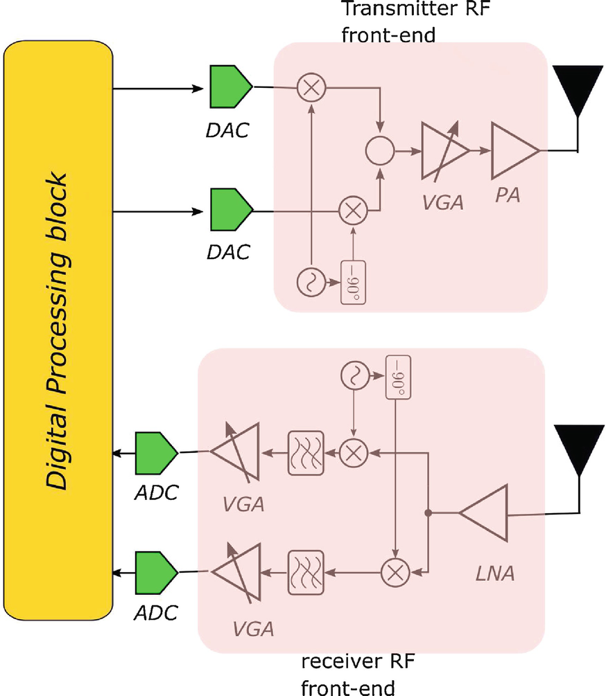
The figure-2 depicts basic block diagram of 5G cell phone architecture. As shown the architecture include baseband part, digital RF interface such as DigRF, ADC/DAC and RF Transceiver. The basic components are same in the 5G phone except antenna array is used instead of one antenna to support massive MIMO and beamforming.
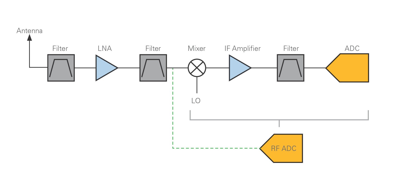
Block diagram of a superheterodyne receiver. The RF front end consists of the components on the left colored red. In a radio receiver circuit, the RF front end, short for radio frequency front end, is a generic term for all the circuitry between a receiver's antenna input up to and including the mixer stage.
Multi-band Sub-GHz RF Front End www.semtech.com Figure A: SX1250 Block Diagram General Description The SX1250 is a sub-GHz RF Front End device designed to work along with Semtech's SX1302 baseband engine, to design a high-performing LoRa® or LoRaWAN gateway. It covers any frequency band below 1 GHz, making it the
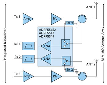
M-MIMO RF front-end block diagram. Wide Operation Bandwidth ADRF5545A/ADRF5547/ADRF5549 gain characteristics of each device and their respective frequency coverage is shown in Figure 2. Parts are optimized for commonly used cellular bands and aligned with other tuned components used in the same design, such as power amplifiers and filters.
high performance RF front end for low-power and low-voltage wireless applications in the 2.4-GHz band. Its single-ended RF input and output make it compatible with any manufacturer's transceiver if appropriate external parts are used. When a transmit/receive (T/R) switch and a balun are used, it can interface with existing and
Fig. 1. 4G/5G RF front end diagram. • Improve the power efficiency for mmWave FR2 radios; most probably FR2 will be used mainly for downlink in mobile applications [10, 11]. • Increase the number of antennas to 6-8 with the requirement to reach these antennas from different 4G/5G LTE radios which have to coexist with multiple
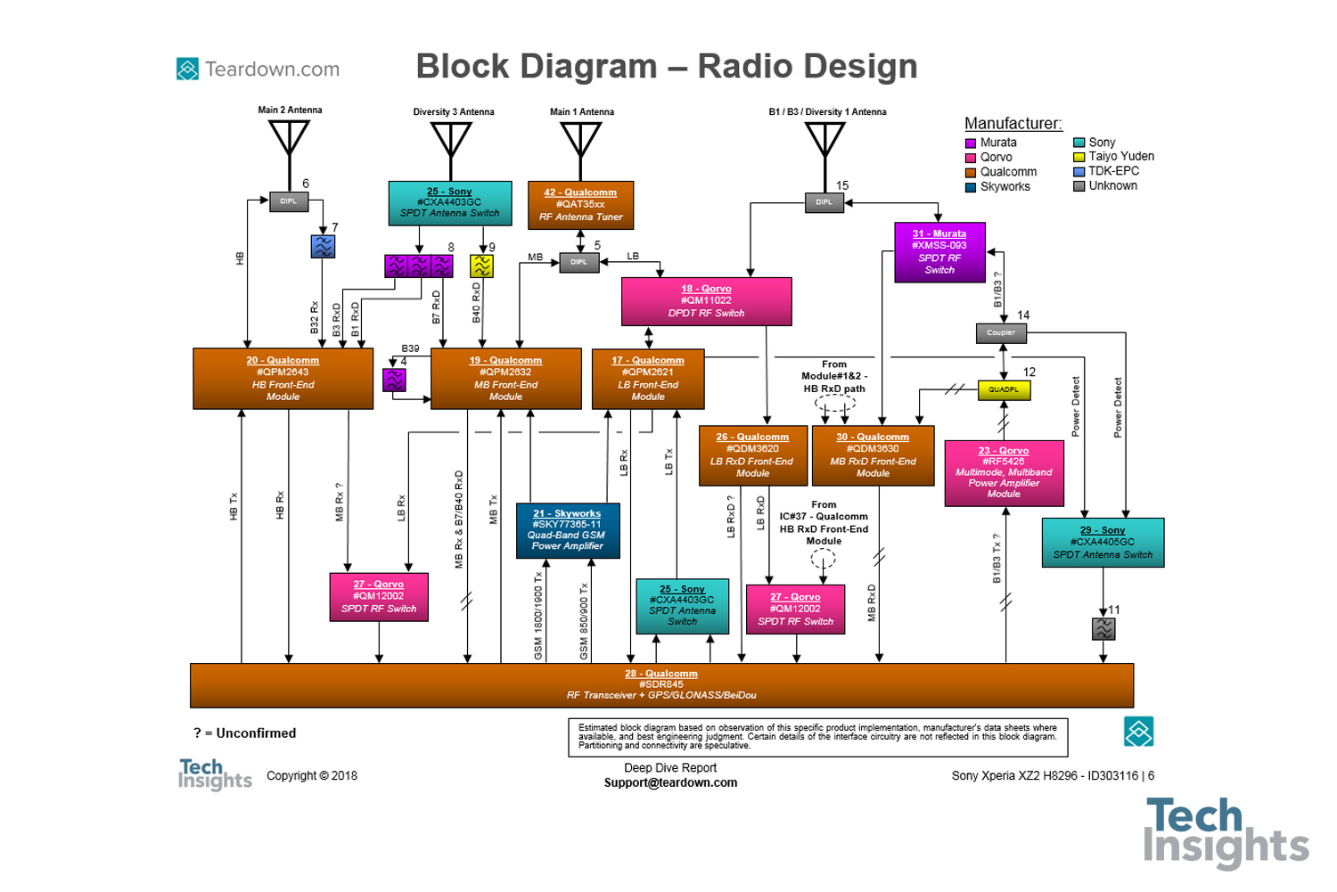
RF Switch is Partitioned by Band to Allow for Diplexing of Bands Front End Block Diagram CA the Three Bands LB -699 to 960 MHz MB -1428 to 2170 MHz HB -2300 to 2690 MHz J. Young "arrier Aggregation, Quantifying Front End Losses," IWPC Chicago Meeting Sept. 16, 2014 2, 3, 4G Module LB GGE MB GGE B1 B4 B25 B3 B8 B20 B26 B12
Low Power Digital I and Q RF Multi-PHY Mode Transceiver www.semtech.com Figure A: SX1257 Block Diagram General Description The SX1257 is a highly integrated RF front-end to digital I and Q modulator/demodulator Multi-PHY mode transceiver capable of supporting multiple constant and non-constant envelope modulation schemes. It is designed
RF Communication Systems • Half-duplex RF Systems Operation mode of a radio communication system in which each end can transmit and receive, but not simultaneously. Note: The communication is bidirectional over the same frequency, but unidirectional for the duration of a message. The devices need to be transceivers.
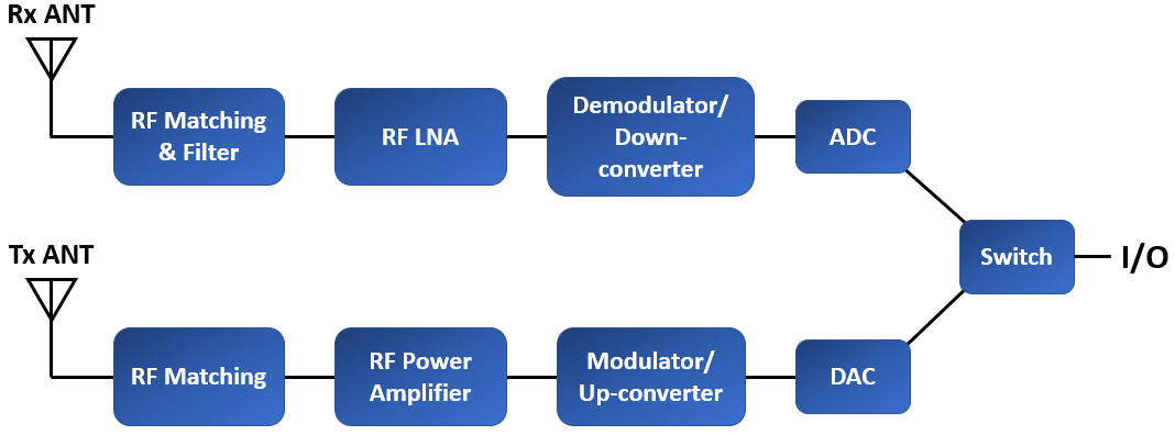
The RF front end contains a number of components that work together to ensure signal integrity throughout the signal's bandwidth. This includes preparing a signal for transmission, as well as receiving and demodulating a signal received on the Rx side. The functional block diagram below shows the general topology of an RF front end.
Integrating more functions into a front-end module (FEM) or filter modules helps to simplify the RF design, as shown in the next block diagram. (A bonus? Integrating the right filter technology inherently helps manage the coexistence issues we discussed earlier, as well as thermal challenges.)
Design of Reconfigurable Radio Front-Ends Xiao Xiao Electrical Engineering and Computer Sciences University of California at Berkeley Technical Report No. UCB/EECS-2018-142
2 LTE RF Front-End Design Challenges ... As shown in the simplified diagram below, the key front end components are power amplifiers (PA) and transmit/receive path or duplex filters and switches for band selection or antenna switch module. Figure 1. Simplified Front -End Block Diagram . From UMTS to LTE and beyond, the RF component technologies ...
Below is a general block diagram for GPS functionality in a device. From the antenna looking into GPS receiver, the ESD device protects the RF front-end against ESD hazards coming from ANT when it makes contact with the external environ-ment. In modern wireless handheld systems, 8 kV contact dis-
3 shows a typical block diagram of a DSMBGA front-end module with integrated duplexer (FEMiD) and a power amplifier module with integrated duplexer (PAMiD). To provide the high level of integration noted above, several enabling technologies were combined to create a DSMBGA front-end module. By utilizing strip grinding, molded underfill (MUF) and
Qualcomm Technologies offers an extensive RF Front End portfolio engineered to deliver integrated solutions for industry-leading RF performance. Our portfolio of power amplifier modules, front-end modules, and diversity receive modules is designed to support virtually all sub-6 GHz and mmWave bands in highly integrated configurations, while ...
Download scientific diagram | (a) Simplified block diagram of the RF front-end. (b) Frequency plan. from publication: A 900-MHz transceiver chipset for two-way paging applications | A 900-MHz ...
Modeling RF Front End in Radar System Simulation. In a radar system, the RF front end often plays an important role in defining the system performance. For example, because the RF front end is the first section in the receiver chain, the design of its low noise amplifier is critical to achieving the desired signal to noise ratio (SNR).
Pasternack's library RF and microwave block diagram are designed to provide engineers and designers with examples of common RF systems schematics while illustrating the RF products and where they fit into the system's design.
The RF front end is generally defined as everything between the antenna and the digital baseband system. For a receiver, this "between" area includes all the filters, low-noise amplifiers (LNAs), and down-conversion mixer(s) needed to process the modulated signals received at the antenna into signals suitable for input into the baseband analog ...



![Solved [50 points] A dual-band radio handset has an RF ...](https://d2vlcm61l7u1fs.cloudfront.net/media%2F546%2F546a358f-4da7-45df-be3d-729bc15864f3%2FphpVrp8LR.png)







0 Response to "38 rf front end block diagram"
Post a Comment