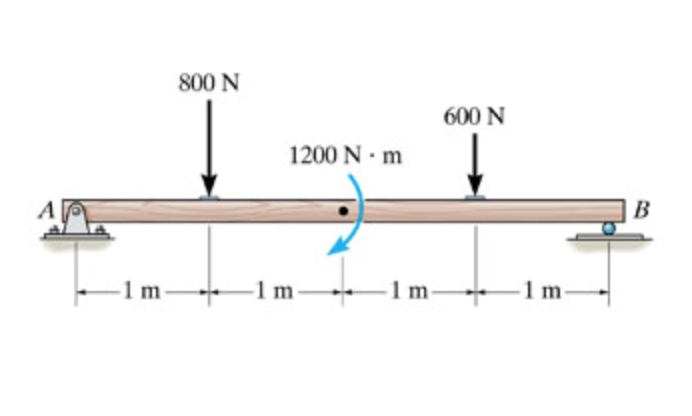
37 draw the shear diagram for the beam. follow the sign convention. (figure 1)
Draw the shear diagram for the beam follow the sign convention figure 1 on add vertical line off to add discontinuity lines lecture note course code bce 306 structural analysis 2 3 under revision disclaimer this document does not claim any originality and cannot be used as a substitute for prescribed textbooks the information. Part A Draw the shear diagram for the beam. Follow the sign convention. (Figure 1) Part B Draw the moment diagram for the beam. Follow the sign convention.
Note 1- You should not draw an "extra" discontinuity line at the point where the curve passes the x-axis. Note 2. The curve you; Question: Problem 7.64 Part A Draw the shear diagram for the beam. Follow the sign convention. (Eiguro 1) Click on "add vertical line off" to add discontinuity lines.
Draw the shear diagram for the beam. follow the sign convention. (figure 1)
Follow the sign convention. Draw the shear diagram for the beam. Draw the shear diagram for the beam follow the sign convention figure 1 on add vertical line off to add discontinuity lines lecture note course code bce 306 structural analysis 2 3 under revision disclaimer this document does not claim any originality and cannot be used as a ... Part A Draw the shear diagram for the beam. Follow the sign convention. (Figure 1) Click on "add vertical line off" to add discontinuity lines. Then click on " ...1 answer · 0 votes: 6 ft 3ft Shear force diagram (kip) -7.50 Mmax=2.45 Bending moment diagram (kip-ft) EMA = 0: - (3 *6/2) * (6 - (1/3)*6) + R$*6 - 2*3*(6 + 3/2) = 0 Rp ... Part A Consider the beam shown in (Figure 1). Follow the sign convention. Draw the shear diagram for the beam Click on "add vertical line off" to add discontinuity lines. Then click on "add segment" button to add functions between the lines. Note 1-You should not draw an "extra" discontinuity line at the point where the curve passes ...
Draw the shear diagram for the beam. follow the sign convention. (figure 1). Note 1 - You should not draw an "extra" discontinuity line at the point where the curve passes the x-axis. Note 2 - The curve you; Question: Problem 7.59 Part A Draw the shear diagram for the beam. Follow the sign convention. (Figure 1) Click on 'add vertical line off to add discontinuity lines. Solution for Draw the shear diagram for the beam. Follow the sign convention. (Figure 1) Click on "add vertical line off" to add discontinuity lines. Problem 7.84 Draw the moment diagram for the beam. Follow the sign convention. Click on "add vertical line off" to add discontinuity lines. Then click on "add segment" button to add functions between the lines. Note 1 - Draw a vertical line to denote local maximum or minimum. shear force and bending moment and also some basic concepts of strength of materials in our recent posts. We have already seen the various types of beams and different types of loads on beam during our previous posts. Today we will see here the sign conventions for shear force and bending moment diagram in subject of strength of materials with the help of this post.
Figure 1 click on add vertical line off to add discontinuity lines. Follow the sign convention. Problem 770 draw the shear diagram for the beam. Part a draw the moment diagram for beam follow sign. Note 2 you should not draw an extra discontinuity line at the. B draw the moment diagram for the beam. Answer to: Part A Draw the shear diagram for the beam. Follow the sign convention. (Figure 1) Click on ?add vertical line off? to add...1 answer · Top answer: First of all, calculating the vertical reactions at A and B support Taking moment about A {eq}R_{B}\times30=20\times45+4\times30\times\dfrac{30}{2}-... Home › draw the shear and moment diagram for the beam › draw the shear diagram for the beam › draw the shear diagram for the beam. 7.78 › draw the shear diagram for the beam. assume that m0=200 lb⋅ft and l=20ft › draw the shear diagram for the beam. assume that w0=10kip/ft and l=18ft › draw the shear diagram for the beam. follow ... Draw the shear diagram for the beam follow the sign convention figure 1. Answer to problem 759 part a draw the shear diagram for the beam. And 2 draw the shear force and bending moment diagrams. Solution note that the triangular load has been replaced by is resultant which is the force 05 12 360 2160 lb area under the loading diagram acting at ...
Jan 28, 2021 — 1 Answer to Draw the moment diagram for the beam. Follow the sign convention. (Figure 1)Click on "add vertical line off" to add ... Question: Problem 7.59 Part A Draw the shear diagram for the beam. Follow the sign convention. (Figure 1) Part B Draw the moment diagram for the beam. These draw the shear and moment diagram for the beam can be used to easily determine the type size and material of a member in a structure so that a given set of loads can be supported without structural failure. Draw the shear diagram for the beam. Follow the sign convention. Figure 1 click on add vertical line off to add discontinuity lines. Draw the shear diagram for the beam. Compute the reaction forces and moments. Assume the support at is a pin. Follow the sign convention. Then click on add segment button to add functions between the lines. If there is an upward force ie a support then the sfd will start at this force above the x axis.
Then draw the shear force diagram sfd and bending moment diagram bmd. For drawing a bending moment diagram or bmd we use a positive sign for the sagging bending moment and a negative sign for the hogging bending moment as shown in the figure below. Follow the sign convention. B if p 20 kn and l 6 m draw the sfd and bmd for the beam.
Answer to Draw the shear diagram for the beam. Follow the sign convention. (Figure 1) Draw the moment diagram for the beam. Follow the sign convention.
Part A Draw the moment diagram for the beam. Follow the sign convention. Part B Draw the shear diagram for the beam. Follow the sign convention.
(A) Draw the shear diagram for the beam. Follow the sign convention. Figure shown below (B) Draw the moment diagram for the beam. Follow the sign convention.
Draw the shear diagram for the beam follow the sign convention figure 1 on add vertical line off to add discontinuity lines lecture note course code bce 306 structural analysis 2 3 under revision disclaimer this document does not claim any originality and cannot be used as a substitute for prescribed textbooks the information.
Since a distributed load varies the shear load according to its magnitude it can be derived that the slope of the shear diagram is equal to the magnitude of the distributed load. Jan 28, · Step 2: Construct the shear force diagram for the beam with these reactions. Step 3: Using the shear force diagram, construct the bending moment diagram.
Consider the beam shown in figure 1. Draw the shear diagram for the beam follow the sign convention figure 1. This is done using a free body diagram of the entire beam. Figure 1 draw the moment diagram for the beam. 1 answer below. Then click on add segment button to add functions between the lines. Draw the shear and moment diagrams for the beam.
Part A Consider the beam shown in (Figure 1). Follow the sign convention. Draw the shear diagram for the beam Click on "add vertical line off" to add discontinuity lines. Then click on "add segment" button to add functions between the lines. Note 1-You should not draw an "extra" discontinuity line at the point where the curve passes ...
Part A Draw the shear diagram for the beam. Follow the sign convention. (Figure 1) Click on "add vertical line off" to add discontinuity lines. Then click on " ...1 answer · 0 votes: 6 ft 3ft Shear force diagram (kip) -7.50 Mmax=2.45 Bending moment diagram (kip-ft) EMA = 0: - (3 *6/2) * (6 - (1/3)*6) + R$*6 - 2*3*(6 + 3/2) = 0 Rp ...
Follow the sign convention. Draw the shear diagram for the beam. Draw the shear diagram for the beam follow the sign convention figure 1 on add vertical line off to add discontinuity lines lecture note course code bce 306 structural analysis 2 3 under revision disclaimer this document does not claim any originality and cannot be used as a ...


0 Response to "37 draw the shear diagram for the beam. follow the sign convention. (figure 1)"
Post a Comment