38 electric temperature gauge wiring diagram
GlowShift | How To Install A Water Temp Gauge - YouTube This video will walk you through the process of installing a Glowshift 7 Color Series Water Temperature Gauge into your vehicle.Shop Water Temperature Gauges... PDF 0 515 012 123 -- Electric Gauges - VDO Instruments Temperature, Pressure or Fuel Gauge (2⁵⁄₈" [66 mm] diameter) 1 2. Lamp Socket (Push in, wedge-type) 1 3. Light Bulb (12-volt / G.E. #158 or equivalent) 1 4. VDO Spin-Lok™ Clamp or mounting bracket 1 5. Installation Instructions 1 CAUTION: Read these instructions thoroughly before making installation. Do not deviate from assembly or ...
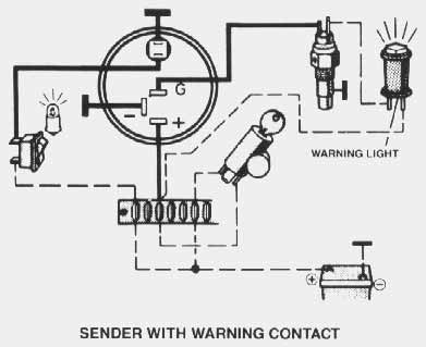
Autometer Water Temp Gauge Wiring Diagram MRC1 · MRC1 - Negative Coil Trigger Diagram · Nitrous Staging Diagram. is beneficial to add a T-fitting to install your new gauge and to keep the warning light operational. A. Water Temp: Install temperature sender (included). Instructions for: Temperature 2 1/16” Spek Pro Professional Racing Gauge .
Electric temperature gauge wiring diagram
Autometer Trans Temp Gauge Wiring Diagram Feb 12, 2018 · Autometer Egt Wiring Diagram. Temp: Hole may have to be drilled, and adapter nut welded or brazed in pan. Be sure. With pressure gauges it is beneficial to add a T-fitting to install your new gauge and to keep the warning light operational. B. Oil & Trans. Temp: Hole may have to be drilled and adapter nut (included) welded or brazed in pan. Electric Temperature, Pressure or Fuel Gauge ... - Academia.edu Electric Temperature, Pressure or Fuel Gauge Installation Instructions Tools and Materials Needed For Installation Temperature/Pressure Gauge Wiring 2 Pages Tehseen Javed oil temp gauge wiring diagram oil temp gauge wiring diagram. oil temp gauge wiring diagram. 2022-02-28; 1、 General rules of automobile wiring. Generally, single line system, parallel connection of electric equipment, negative grounding, lines are distinguished by lines and numbers with different colors, and divided into several trunk lines centered on the ignition switch ...
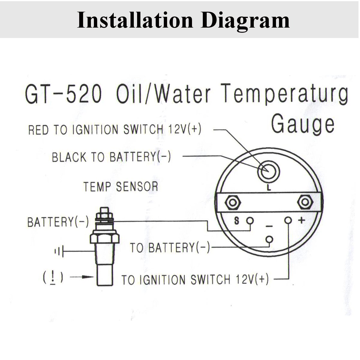
Electric temperature gauge wiring diagram. COOLANT TEMPERATURE GAUGE AND SENSOR ... - ISSPRO it in backwards far enough to make an electrical connection which may damage the gauge! 10 Secure all wiring so that it does not interfere with moving parts ...2 pages General Motors temperature gauge troubleshooting - American Autowire Temperature gauge troubleshooting begins with isolating the problem either to the gauge, sending unit, fuse or wiring. As with any electrical troubleshooting it is best to check all wiring connections are clean, tight and free of corrosion. The following process must be preformed with the ignition key turned to the "on" position. Installing an Electric Water Temp. Gauge | DSMtuners.com With an electric water temp gauge, youre sposed to use/buy a temperature sending unit. A lot of people drill their thermostats and thread the sending unit in. They you just run a wire from the sending unit to the guage. Ground another wire (from the gauge) and then run a 12v power source to it. Thats pretty much it. Feb 24, 2004 #3 dsmturboawd PDF INSTALLATION INSTRUCTIONS SHORT SWEEP ELECTRIC GAUGES - Autometer SHORT SWEEP ELECTRIC GAUGES 2650-1079-00 Rev. C Mounting ... Temperature Gauges TEMPERATURE SENDER USE TEFLON SEALING COMPOUND ON PIPE 1. Install temperature sender. THREADS ... 10 gauge wire or larger must be used. Caution: Do Not over tighten nuts on back of gauge. +-Wiring
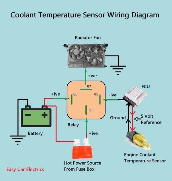
How to install an oil temperature gauge | How a Car Works Drain the engine oil. Fit the plug adapter in place of the plug. Screw the temperature sender unit into the adapter and join the wire to the terminal on the sender unit. Refill the engine with oil and test the system. If you need to drill an extra hole in the sump for the sender. wiringdiagram.2bitboer.com › electric-temperatureElectric Temperature Gauge Wiring Diagram Electric Temperature Gauge Wiring Diagram. By Admin | October 21, 2017. 0 Comment. Installation instructions temperature gauge part 13009 replacing old vdo temp with new wiring question downeast boat forum troubleshooting gauges instrumenteters boatus for derale etrailer com 2 inch 52mm digital car red led electronic water and sensor alexnld ... schematron.org › vdo-temperature-gauge-wiringVdo Temperature Gauge Wiring Diagram/ - schematron.org Jan 10, 2018 · Temperature gauge, pressure gauge, rudder angel gauge, A specialized technician should install the product. according to the electrical wiring diagram. Buy VDO A2CS Temperature Gauge: Gauges - schematron.org FREE DELIVERY possible on eligible No wiring diagram or bezel included. VDO Wiring Diagrams - Diagram will open in a new window. Fuel … How To Properly Wire Electric Cooling Fans The temperature sender, if used, is designed to provide a ground signal at about 185 degrees, and will shut back off when the temperature drops below 165 degrees. This wire (gray in our kit) supplies the ground signal to trigger the relay. The orange wire on the relay should see a 12 volt signal when the ignition switch is turned on.
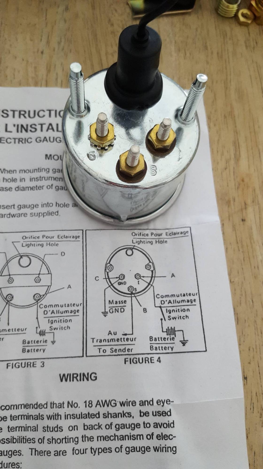
INSTALLATION INSTRUCTIONS FULL SWEEP ELECTRIC … 2. into connector of temperature sender prior to connecting harness. Disconnect the negative (-) battery cable. 3. Gauge mounts in a 2-1/16" hole for the 2-1/16" gauges and a 2-5/8" hole for the 2-5/8" gauges. Use supplied brackets and nuts to secure gauge to dash. 4. 9. Drill 1” diameter hole where wires pass through sheet metal How to Install an Engine Water Temp Gauge - It Still Runs Step 1. Choose a location for the temperature gauge mounting hole on the vehicle dashboard. Ensure that the gauge will be visible and that no wires or hoses behind the dash will be damaged when drilling the mounting hole. Use a drill and hole saw to make a 2 1/16 or 2 5/8 inch hole (depending on the gauge model) in the dashboard at the chosen ... › coolant-temperature1, 2, & 3 Wire Coolant Temperature Sensor Wiring Diagram 3 Wire Coolant Temperature Sensor Wiring Diagram. The two wires, a “5-volt reference”, and a “ground wire” go to the ECU, and the third wire “Earth Signal Wire for Temperature Gauge” goes to the cluster-mounted temperature gauge by providing an earth signal to the temperature gauge. In three wire coolant temperature sensors, the ECU ... SHORT SWEEP ELECTRIC GAUGES - Autometer White Wire: Connect to +12 Volt Lighting. INSTALLATION INSTRUCTIONS. SHORT SWEEP ELECTRIC GAUGES. 2650-1079-00 Rev. C. Mounting.
VDO Performance Instruments
Dolphin Gauges Wiring Schematic - Wiring Diagram and Schematics Gauge Wiring Question The Hull Truth Boating And Fishing Forum ... 66 c10 american auto wire kit install gm cable gauge question the hull truth manuals vdo equipment marine smiths electric oil temperature 1951 technical tachometer h rewiring fuel ford truck 5 piece grey programmable set grumman tiger cheetah mounting gps tach hm enthusiasts ...

Corvette Temperature Gauge Required Input 1979 | Willcox ...
Vdo Water Temp Gauge Wiring Diagram the sender body, or backwards, the fuel gauge will read "full" when the temperature sender refer to the wiring diagram, diagram g. wire gauges in series from a positive (+) temperature: needle to the temperature of the engine water.using the expertise we've gained in developing specialized solutions for many of the world's leading manufacturers, …
Tech Shop
How to Wire a Temperature Gauge | It Still Runs Cut a length of wire that will reach from the fuse box to the gauge location. Strip both ends of the wire. Twist one end of the wire and place it under the spade fuse connector. Step 9 Use wire cutters to cut a notch in the bottom lip of the fuse box lid and place the wire in the notch as you refasten the fuse box lid.
Troubleshooting Oil Pressure and Water Temperature Gauges
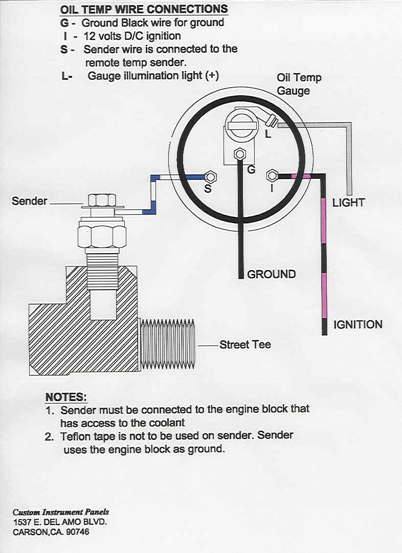
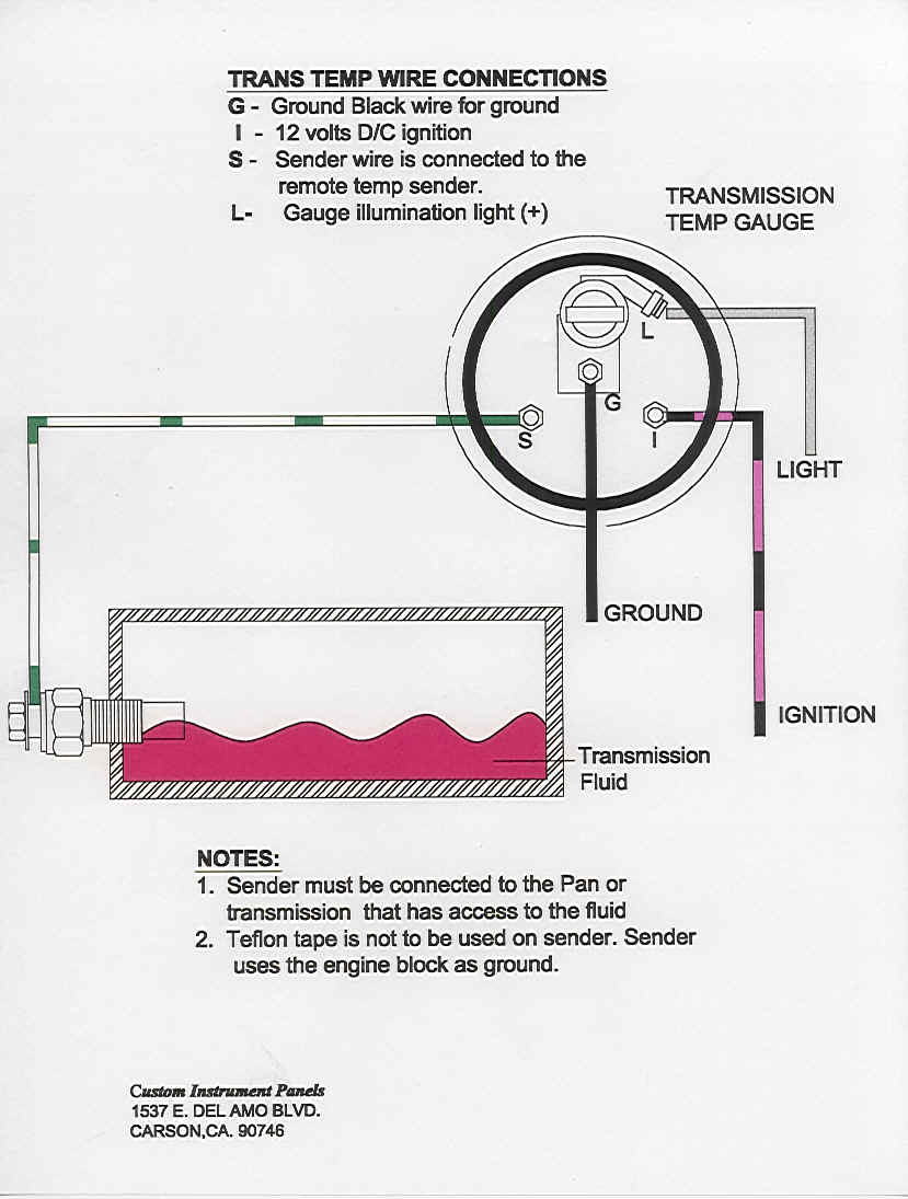
Traditional Electric Gauge - Stewart Warner TEMPERATURE GAUGE WIRING (Figure 3): 1. Disconnect negative (-) battery cable. 2. Using 18-ga. wire, connect the (G) terminal to a clean (rust/paint-free) ground surface near the temperature sender. 3. Using 18-ga. wire, connect the (I) terminal to a switched +12V source. 4. Using 18-ga. wire, connect the (S) sender terminal of the

White 7 Color Water Temperature Gauge
Wiring Diagrams - Classic Instruments Wiring Diagrams. 01 Six Gauge Set Wiring Diagram 11/10/09. 01 Six Gauge Set Wiring Diagram 5/9/19. Six Gauge Set Wiring Diagram SNWH03 . All-American 3200/6400 Package Guide Rev 2/27/13. Download 3200 Wiring Instructions Rev 2/7/13. Download 6400 Wiring Instructions Rev 2/7/13 . Senders . SN11 Low Volt Light Rev 7/12/12
Vintage Chrysler electrical repairs and updates
› wiring-diagram-for-smithsWiring Diagram For Smiths Temperature Gauge Oct 31, 2019 · Instructions For 52mm Electrical Gauges Smiths 12v 2 52mm Classic Car Temperature Gauge 13h4460 Smiths Classic Gauges Updating Smiths Dash Gauge Voltage Iliser Abs Zero Smiths Electric Oil Temperature Gauge From Competition Supplies Worldwide Shipping Available Morgan 4 8 Aero Car Wiring Diagrams Spares Com
Installation Instructions
PDF 3.0 3.0 Installation Instructions Electrical Gauges/Kits Temperature NOTE: Wire for gauge lights must be purchased separately. Use size 18-20 AWG stranded copper wire. 2. Splice the RED or WHITE wire from the gauge light(s) into the vehicle's lighting circuit, between the dimmer control switch and the dash lights (consult the vehi-cle's service manual for proper wire). 3 GAUGE LIGHT INSTALLATION AND CONNECTION3.
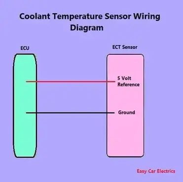
1, 2, & 3 Wire Coolant Temperature Sensor Wiring Diagram
PDF WATER TEMPERATURE - SAAS Automotive Wiring Diagram Ignition harness / Fuse box Red Ignition 12V+ Green Sensor input- Ignition harness / Fuse box Water temp sender output (red wire of sender) SAAS Automotive PTY LTD Colour change button Note: Colour change button is on the front for Series II gauges.

Pin on Electrical system
wiringall.com › vdo-temperature-gauge-wiringVdo Temperature Gauge Wiring Diagram/ Diagram C Proper Wiring Between Gauge and Pressure Sender II. Wiring the VDO Universal Pressure Sender 1. Either run a new wire to the pressure gauge or find the existing wire if a pressure gauge is ready to be installed. 2. Crimp a ring terminal onto the sender end of wire. 3.

1, 2, & 3 Wire Coolant Temperature Sensor Wiring Diagram
Autometer Water Temp Gauge Wiring How to Install an Auto Meter Pro-Comp Ultra-Lite Water Temp Gauge - Electric on Your Musta double check that all connections are tight. After starting engine, check wiring connections for hot spots. Be prepared to shut engine off immediately if hot spots are detected. Fuel level. 1. Gauge connects to fuel sender on fuel tank.

E-Type Fuel, Temp, Oil, Ammeter Gauge Wiring Diagram Symbols ...
Gauges - Wiring Guides | REDARC Electronics REDARC has a library of wiring guides and installation setups for our range of monitoring gauges. Installing 52mm Gauges into a location without Dash or Park lights GA-ELC Dimming Gauges in Reverse

Oil, Temperature, Voltage gauges for your bike
oil temp gauge wiring diagram oil temp gauge wiring diagram. oil temp gauge wiring diagram. 2022-02-28; 1、 General rules of automobile wiring. Generally, single line system, parallel connection of electric equipment, negative grounding, lines are distinguished by lines and numbers with different colors, and divided into several trunk lines centered on the ignition switch ...

Temperature Indicators (Automobile)
Electric Temperature, Pressure or Fuel Gauge ... - Academia.edu Electric Temperature, Pressure or Fuel Gauge Installation Instructions Tools and Materials Needed For Installation Temperature/Pressure Gauge Wiring 2 Pages Tehseen Javed

Morgan +4, 4/4, +8, Aero 8 Car Wiring Diagrams | morgan ...
Autometer Trans Temp Gauge Wiring Diagram Feb 12, 2018 · Autometer Egt Wiring Diagram. Temp: Hole may have to be drilled, and adapter nut welded or brazed in pan. Be sure. With pressure gauges it is beneficial to add a T-fitting to install your new gauge and to keep the warning light operational. B. Oil & Trans. Temp: Hole may have to be drilled and adapter nut (included) welded or brazed in pan.

2” Electrical Water/Oil Temperature Gauge | Bosch Style Line

Transmission Tempature Gauge

1, 2, & 3 Wire Coolant Temperature Sensor Wiring Diagram
1, 2, & 3 Wire Coolant Temperature Sensor Wiring Diagram

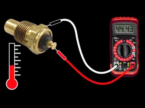
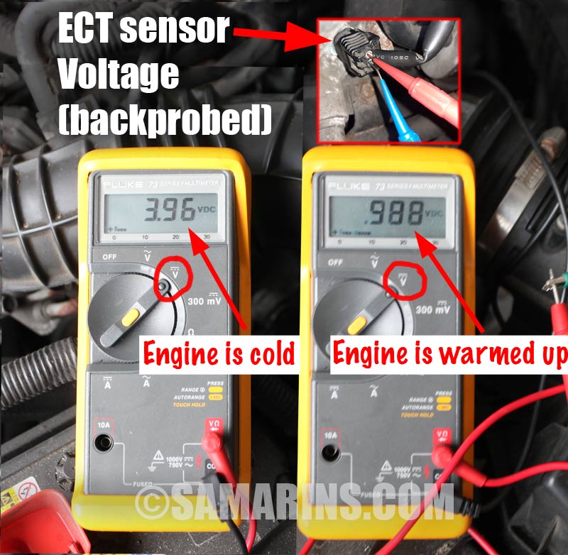
How to test a temperature sensor / sending unit and temperature gauge

Buy ZOZOMOTORS Dual Electric Fan Relay Kit Radiator Electric ...

Im working on a 98 GTP 3.8L Supercharged Gran Prix. The temp ...

Manuals for VDO Equipment - MARINE DIESEL BASICS

Amazon.com: ESUPPORT Car 2" 52mm Digital Water Temp Gauge ...

Wiring Console Gauges' 69
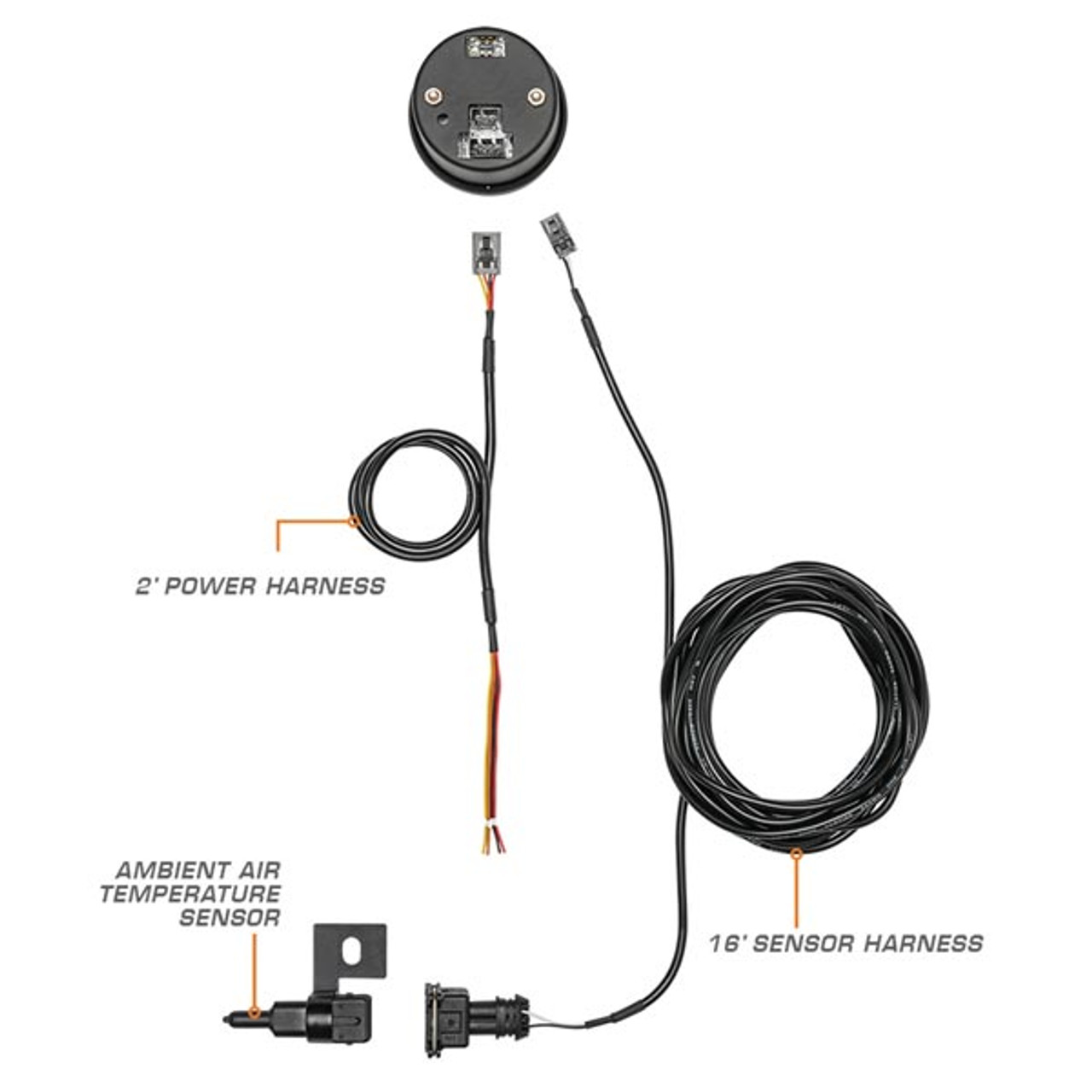
10 Color Digital Ambient Air Temperature Gauge
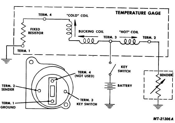
Fig. 20 Water Temperature Gauge Circuit Diagram
Tech Shop

GM Coolant Sensor #12146312 Interface - Sensors - Arduino Forum

Water Coolant Oil Temp Temperature 1/8 NPT Electrical Sender Sending Sensor | eBay
1991 Fuel/Temp gauge issues | Suzuki Forums
Installation Instructions
Installation Instructions
Troubleshooting Boat Gauges, Instruments and Meters | BoatUS
basic wiring - water temp sensor/gauge - help a complete ...
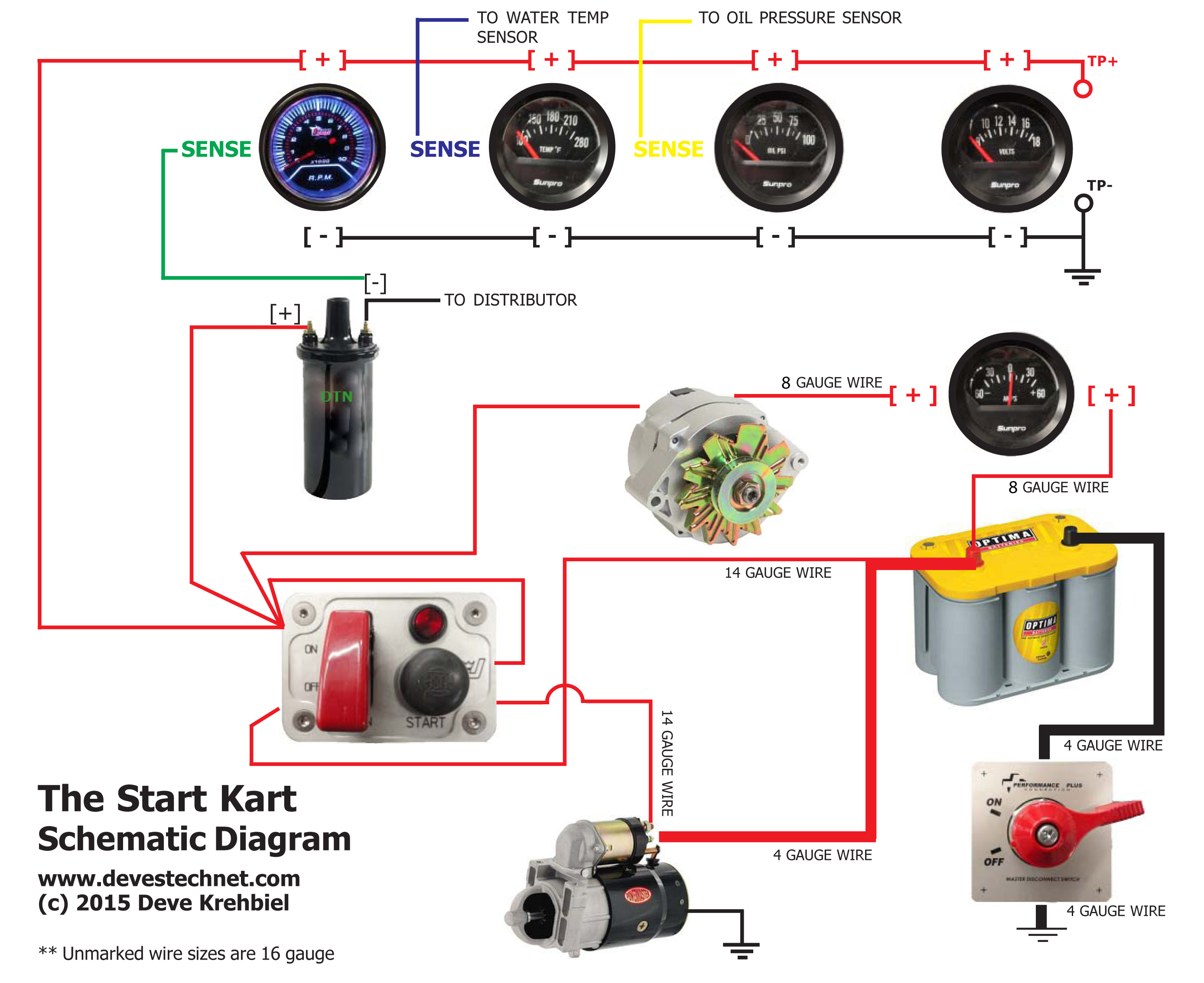
Start Kart Plans
2 Inch 52mm Digital Car Red LED Electronic Water Temp ...
Dash Instrument Testing - Falcon Enterprises
Engine coolant temperature sensor: how it works, symptoms ...
0 Response to "38 electric temperature gauge wiring diagram"
Post a Comment