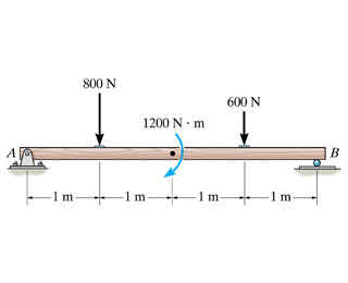
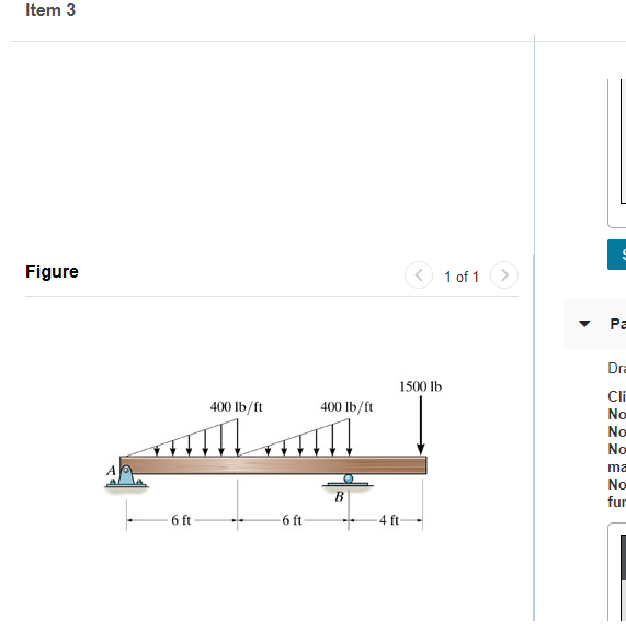
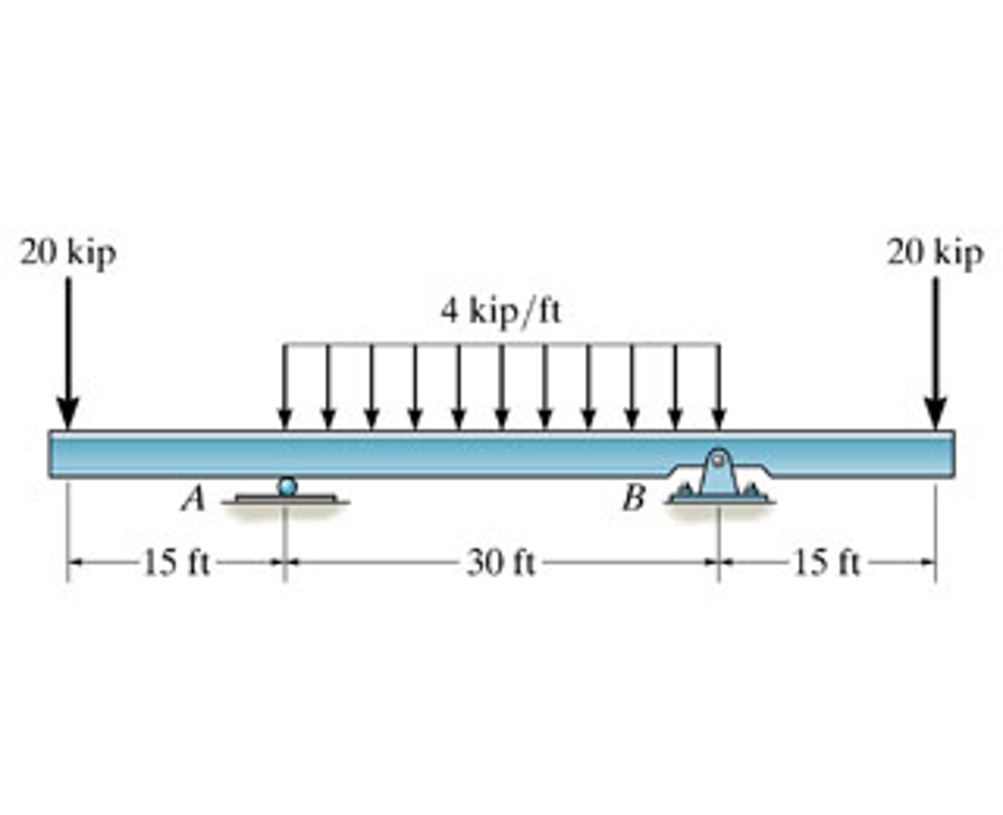
38 draw the moment diagram for the beam. follow the sign convention.
[Solved] Please Draw Sheer and Moment Diagram | Course Hero Please Draw Sheer and Moment Diagram. Image transcription text. Consider the beam shown in (Figure 1). Follow the sign convention. Part A Draw. the shear diagram for the beam. Click on "add vertical line off" to add. discontinuity lines. Then click on "add segment" button to ... › PriodeepChowdhury › prestressedPrestressed Concrete Design - SlideShare Jan 10, 2016 · Design of PSC Members 3.1 Basis Sign Convention In order to derive equations that enable design, we maintain a rigid sign convention: • Moment: Positive sag; • Eccentricity of prestress: Positive above centroid; • Section Modulus: Negative for the bottom of the member; • Stress: Positive compression.
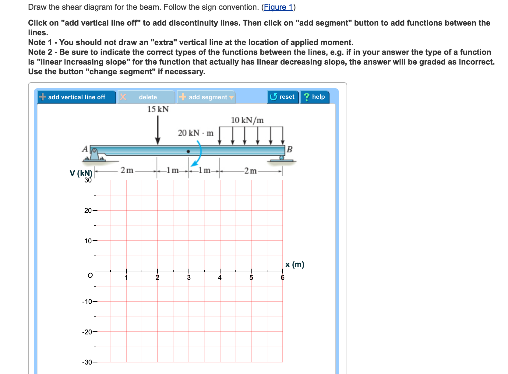
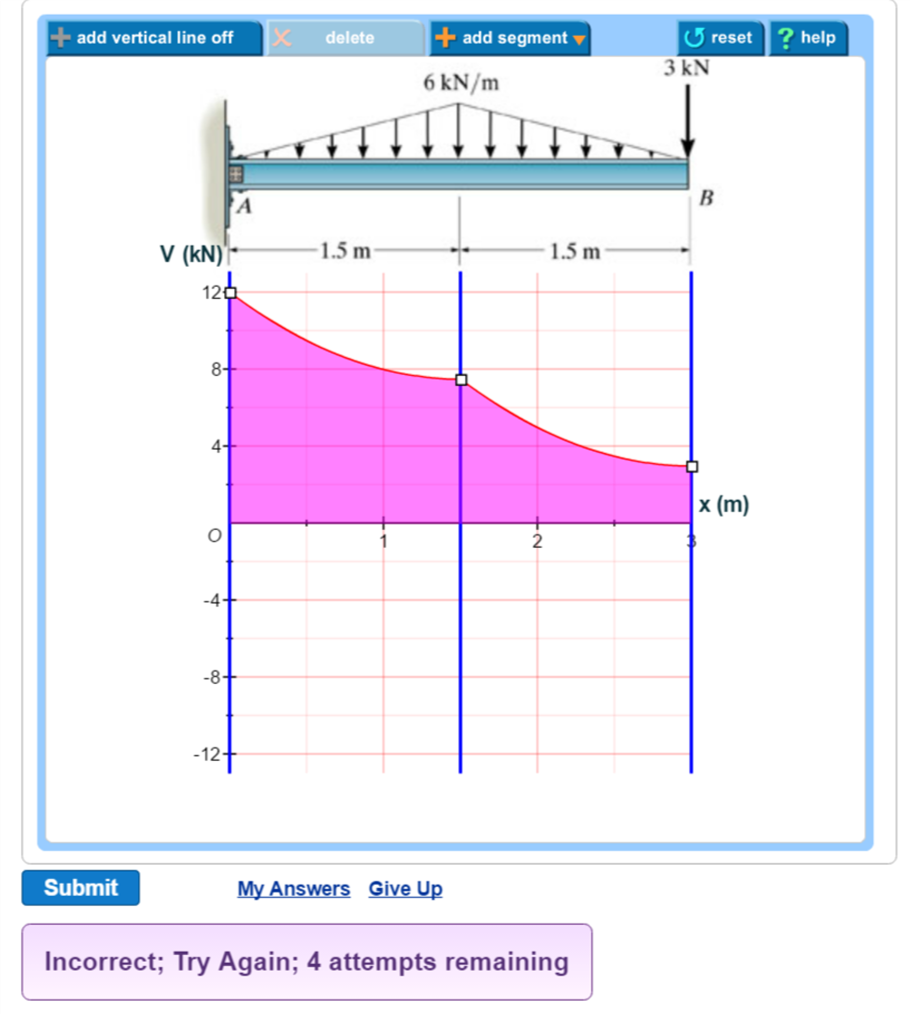
Answered: Part A Draw the shear diagram for the… | bartleby Part A Draw the shear diagram for the beam. Follow the sign convention. (Figure 1) Click on "add vertical line off" to add discontinuity lines. Then click on "add segment" button to add functions between the lines. Note - Make sure you place only one vertical line at places that require a vertical line.
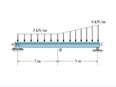
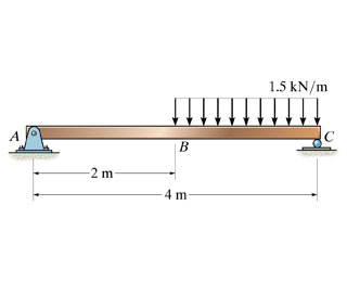
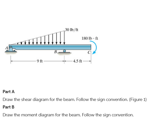
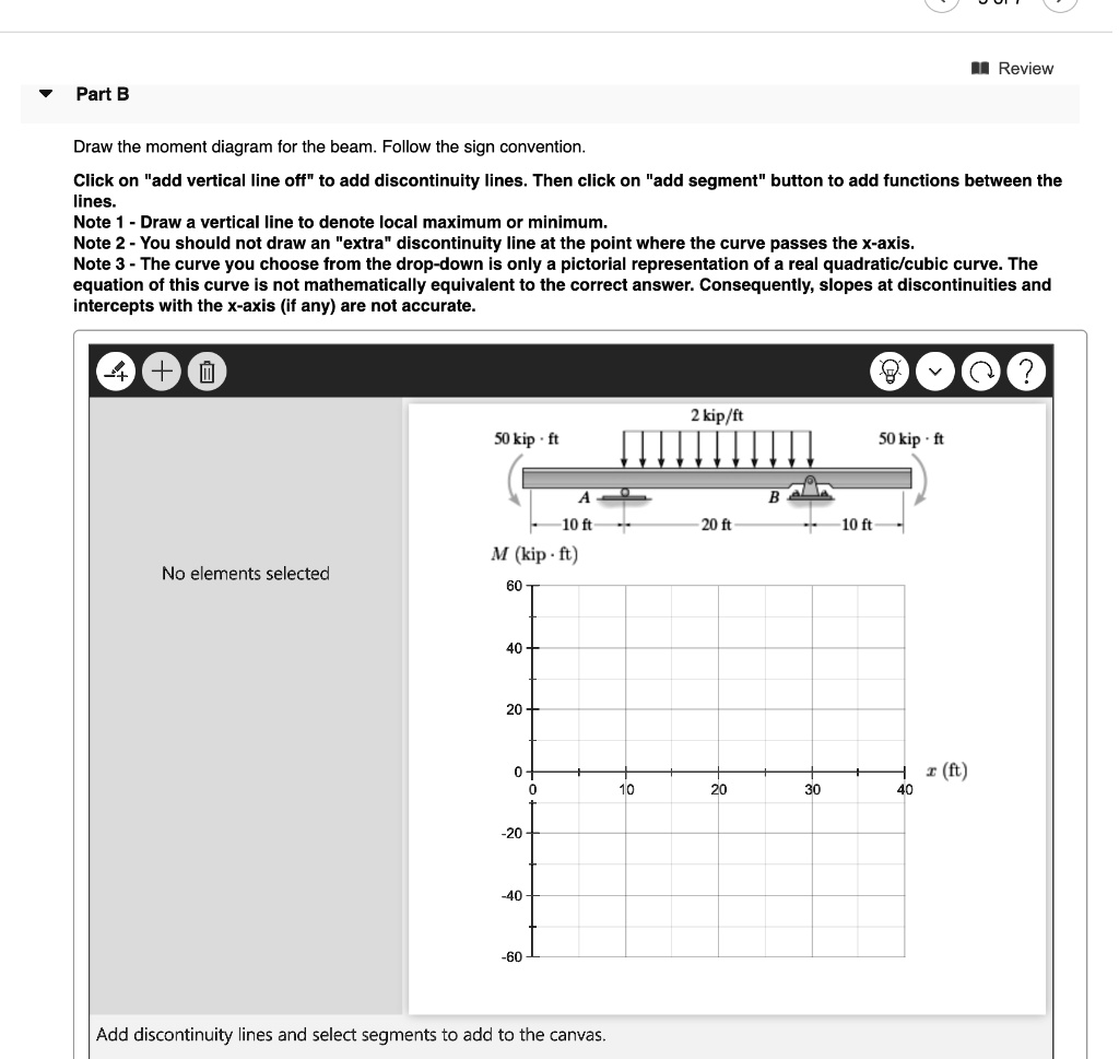
Draw the moment diagram for the beam. follow the sign convention.
PDF Structural Axial, Shear and Bending Moments F.1 (b), the positive sign convention is (a) tension axial force, (b) shear forces that produce clockwise moments and (c) bending moments that result in tension stresses in the interior frame fibers. The sign convention of F.1(b) can be seen to be equivalent to the beam sign convention rotating columns AB and CD to line up with beam BC. engcourses-uofa.ca › shear-and-moment-equationsEngineering at Alberta Courses » Shear and moment equations ... In the FBD, the directions of the unknown force and moment are assumed positive according to the member sign convention. 2- Solve the equations of equilibrium for the support reactions. 3- Make a cut in the FBD of the beam at an arbitrary point x meter away from the left end of the beam as shown. Choose one of the two segments for analysis. › 43134532 › Mechanics_of_MaterialsMechanics of Materials Tenth Edition in SI Units - Academia.edu Enter the email address you signed up with and we'll email you a reset link.
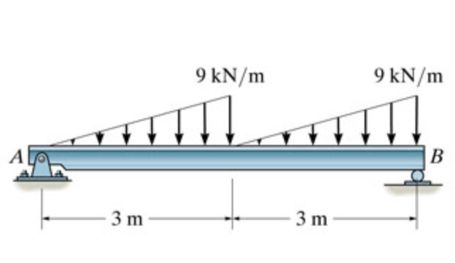
Draw the moment diagram for the beam. follow the sign convention.. › ManthanChavda2 › shear-forceShear force and bending moment diagram - SlideShare May 17, 2018 · Sign Convention for shear force F F F F + ve shear force - ve shear force 8. Sign convention for bending moments: The bending moment is considered as Sagging Bending Moment if it tends to bend the beam to a curvature having convexity at the bottom as shown in the Fig. given below. Sagging Bending Moment is considered as positive bending moment. en.wikipedia.org › wiki › DielectricDielectric - Wikipedia In electromagnetism, a dielectric (or dielectric material or dielectric medium) is an electrical insulator that can be polarised by an applied electric field.When a dielectric material is placed in an electric field, electric charges do not flow through the material as they do in an electrical conductor, because they have no loosely bound, or free, electrons that may drift through the material ... What is the sign convention to draw bending moment diagram of ... - Quora Draw free body diagram. Mark the directions of moments from the sign which you get in moment calculation or whether it is sagging or hogging. Mark the arrows and then draw line equal to magnitude of moment. Always remember draw the diagram on tail side of the arrow. Refer some examples on Google or some standard books to understand better. Consider the frame shown in (Figure 1). Follow the sign convention ... canvas. SubmitRequest Answer Part B Draw the moment diagram for member AB. Follow the sign convention for the internal loadings in the member shown in the figure below. Click on "add vertical line off" to add discontinuity lines. Then click on "add segment" button to add functions between the lines. Note 1 - Make sure you place only one vertical line at places that require a vertical line.
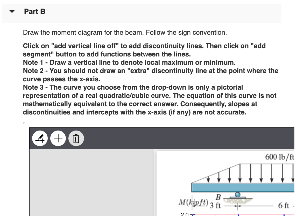
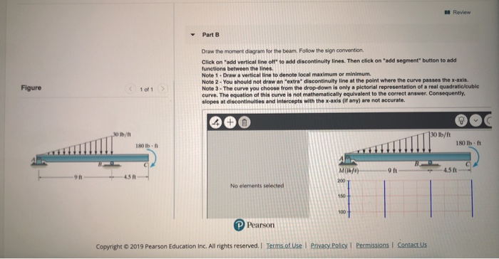
Solved Part B Draw the moment diagram for the beam. Follow | Chegg.com Expert Answer 100% (2 ratings) Transcribed image text: Part B Draw the moment diagram for the beam. Follow the sign convention Click on "add vertical line off" to add discontinuity lines. Then click on "add segment" button to add functions between the lines. Note 1 - Draw a vertical line to denote local maximum or minimum. Solved Problem 7.87 Part A Draw the shear diagram | Chegg.com Engineering. Mechanical Engineering. Mechanical Engineering questions and answers. Problem 7.87 Part A Draw the shear diagram for the beam. Follow the sign convention. Part B Draw the moment diagram for the beam. Follow the sign convention. Question: Problem 7.87 Part A Draw the shear diagram for the beam. Follow the sign convention. › questions-and-answers › draw-theAnswered: Draw the shear diagram for the beam… | bartleby Consequently, slopes at discontinuities and intercepts with the x- axis (if any) are not accurate. 120 lb/ft 30 lb/ft 12 ft No elerments selected V (Ib) 600 500 400 300 200 100 z (ft) 100- Draw the moment diagram for the beam Click on "add vertical line ofr" to add discontinuity lines. › 41819063 › Shigleys_2015Shigley's. 2015. Mechanical Engineering Design. 10th Ed. Enter the email address you signed up with and we'll email you a reset link.
Problem 2 Draw the shear and bending-moment diagrams for the Draw the shear and bending moment diagram of the following beams using Draw the shear and bending moment diagram of the following beams using area method. Also make a summary table for the following values: a. End reactions and moments (R left , M left ,R right , M right ) b. Maximum positive and negative bending moment and locations (measured ... [Solved] Please see attachments for details | Course Hero Part A Draw the shear diagram for the beam. Follow the sign convention. (Figure 1)... Image transcription text ... Drawing SFD Portion AC RA consider section -x a distancex/ from A From properties of, trouingle - Wx ADO = Wx 6 X = S Wy : 200 x 3 3X = RX - 1 x XX 200x 2 3 Su = 500 - 100 x2 3 3 1 ( x = 0 ) : 500lb be ( x = 6 ) = - 700 lb Portion ... Answered: Part B Draw the moment diagram for the… | bartleby Part B Draw the moment diagram for the beam. Follow the sign convention. Click on "add vertical line off" to add discontinuity lines. Then click on "add segment" button to add functions between the lines. Note 1- The curve you choose from the drop-down is only a pictorial representation of a real quadratic/cubic curve. draw the shear diagram for the beam 6.29 - chemistryartdrawingeasy 4 kNm 3 m 3 m A B Prob. Draw the shear and moment diagrams for the beam shown in Fig. Reaction at the support A R A 5 3 7 2 2 6 29 t. Draw the shear and moment diagram of a beam of a 7m-simple span with an overhang of 15m weighs 3P kN per meter is loaded by 3 vertical downward forces. Mechanics of materials solution manual.
Solved Part A Draw the shear diagram for the beam. Follow ...
[Solved] Problem 7.84 Draw the shear diagram for the beam. Follow the ... Problem 7.84 Draw the moment diagram for the beam. Follow the sign convention. Click on "add vertical line off" to add discontinuity lines. Then click on "add segment" button to add functions between the lines. Note 1 - Draw a vertical line to denote local maximum or minimum.

Part A Draw the shear diagram for the beam. Follow the sign ...
Answered: Part B Draw the moment diagram for the… | bartleby Part B Draw the moment diagram for the beam. Follow the sign convention. Click on "add vertical line off" to add discontinuity lines. Then click on "add segment" button to add functions between the lines. Note 1- Draw a vertical line to denote local maximum or minimum.
Solved Draw the shear diagram for the beam. Follow the sign ...
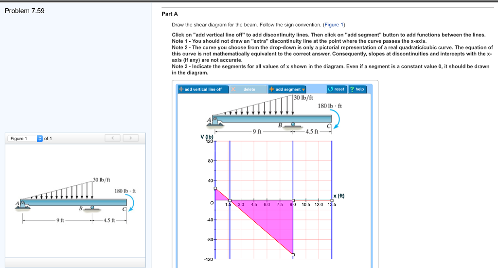
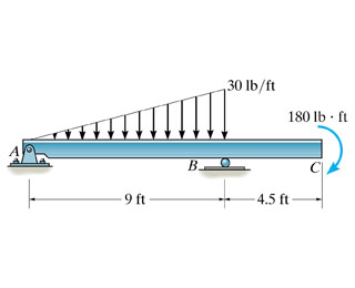
(Solved) - Draw the moment diagram for the beam. Follow the sign ... Draw the moment diagram for the beam. Follow the sign convention. (Figure 1)Click on "add vertical line off" to add discontinuity lines. Then click on "add segment" button to add functions between the lines. Note 1 - You should not draw an "extra" discontinuity line at the point where the curve passes the x-axis.
Solved 1) Draw the shear diagram for the beam. Follow the ...
Shear Moment Diagrams: The Best Guide to Using Them Once again we have a simply supported beam so there will be no moment at the ends. Looking up our end reactions in the beam tables, we find the following. Note, that our moment applied is in the opposite direction of the sign convention. We end up with 5 kip for R 1 and -5 kip for R 2. Now we can draw the shear diagram.

Part A Draw the shear diagram for the beam. Follow the ...
SOLVED:Part B Draw the moment diagram for the beam. Follow the sign ... Follow the sign convention: Click on add vertical line off" to add discontinuity lines_ Then click on add segment" button to add functions between the lines_ Note Draw vertical line to denote local maximum or minimum; Note 2 The curve you choose from the drop-down is only pictorial representation of real quadraticlcubic curve.

a. Draw the shear diagram for the beam in the figure. Follow ...
Answered: Draw the shear diagram for the beam.… | bartleby Draw the shear diagram for the beam. Follow the sign convention. (Figure 1) Click on "add vertical line off" to add discontinuity lines. Then click on "add segment" button to add functions between the lines. Note 1 - You should not draw an "extra" discontinuity line at the point where the curve passes the x-axis.

Draw the moment diagram for the beam. Follow the sign ...
Answered: Draw the shear diagram for the beam.… | bartleby We've got the study and writing resources you need for your assignments. Start exploring! Engineering Mechanical Engineering Q&A Library Draw the shear diagram for the beam. Follow the sign convention. Draw the moment diagram for the beam. Follow the sign convention. Draw the shear diagram for the beam. Follow the sign convention.

Draw the shear diagram for the beam. Follow sign convention ...
Moment Diagram Sign Convention Poll - Eng-Tips Forums RE: Moment Diagram Sign Convention Poll. paddingtongreen (Structural) 11 Feb 11 19:47. putting the BM above the beam was fine, it was positive, below the line was negative. Then I moved on to fixed ended beams and the direction of rotation got a sign, clockwise positive and anti clockwise negative, or vice versa.
Solved Draw the shear diagram for the beam. Follow the sign ...
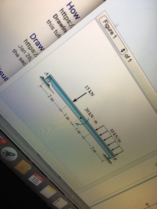
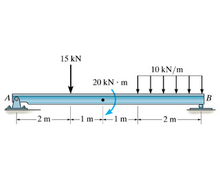
(Solved) - Draw the shear diagram for the beam. Follow the sign... - (1 ... Draw the shear diagram for the beam. Follow the sign convention. (Figure 1) Draw the moment diagram for the beam. Follow the sign convention. 15 kN 10 kN/m 20 kN mm 2 m 2 m 1 Approved Answer HARSH answered on January 21, 2021 5 Ratings, ( 18 Votes) solution .pdf Do you need an answer to a question different from the above? Ask your question!

Draw the moment diagram for the beam. Follow the sign ...
(Solved) - A) Draw the shear diagram for the beam. Follow the... - (1 ... Follow the sign convention. Draw the shear and moment diagrams. Please specify what type of lines are in the diagram (linear, quadratic, etc). 1.5 m 8 kN/m 6 m
Solved Problem 7.56 Part A Draw the shear diagram | Chegg.com
Draw the moment diagram for the beam. Follow the sign | Chegg.com Expert Answer Transcribed image text: Draw the moment diagram for the beam. Follow the sign convention. Click on "add vertical line off to add discontinuity lines. Then click on "add segment" button to add functions between the lines. Note 1 - Draw a vertical line to denote local maximum or minimum.

Part A Draw the shear diagram for the beam. Follow the ...
Draw the shear diagram for the beam. follow the sign convention. Draw a structural formula(s) for the major organic product(s) of the following reaction. Draw a structural formula(s) for the major organic product(s) of the following reaction. Draw the enantiomer of the following compound: Draw the enantiomer of the following compound: Draw the correct bond-line structure for the following compound: Where can ...
Introductory Solid Mechanics TAM 251
Part A Draw the moment diagram for the beam. Follow the sign convention ... Shear and Moment Diagram for a Beam with Distributed Loads: Triangular and rectangular loadings are examples of distributed loads. In this problem, we will use method of area to solve for the ...

Solved) - Draw the shear diagram for the beam. Follow the ...
› 43134532 › Mechanics_of_MaterialsMechanics of Materials Tenth Edition in SI Units - Academia.edu Enter the email address you signed up with and we'll email you a reset link.
Solved Draw the shear diagram for the beam. Follow the ...
engcourses-uofa.ca › shear-and-moment-equationsEngineering at Alberta Courses » Shear and moment equations ... In the FBD, the directions of the unknown force and moment are assumed positive according to the member sign convention. 2- Solve the equations of equilibrium for the support reactions. 3- Make a cut in the FBD of the beam at an arbitrary point x meter away from the left end of the beam as shown. Choose one of the two segments for analysis.
Solved Problem 7.61 Part A Draw the shear diagram for the ...
PDF Structural Axial, Shear and Bending Moments F.1 (b), the positive sign convention is (a) tension axial force, (b) shear forces that produce clockwise moments and (c) bending moments that result in tension stresses in the interior frame fibers. The sign convention of F.1(b) can be seen to be equivalent to the beam sign convention rotating columns AB and CD to line up with beam BC.

Draw the shear diagram for the beam. follow the sign ...
Draw the shear diagram for the beam. Follow the | Chegg.com

Solved) - Part B Draw the moment diagram for the beam. Click ...

Draw shear and bending diagram for the beam given in the ...
Solved Draw the shear diagram for the beam. Follow the ...
Solved Problem 7.59 Part A Draw the shear diagram for the ...
Solved Problem 7.59 Part A Draw the shear diagram for the ...
Solved Draw the shear diagram for the beam. Follow the sign ...

Determine the shear and moment along the beam as functions of ...

Pin on Desk Setups
Solved: solve please Review Part B Draw the moment diagram
Draw the shear diagram for the beam. - StudentShare

For the figure below, draw: a) Draw the shear diagram for the ...

Statics 7.61 - Draw the shear and moment diagrams for the beam.
Internal Forces and Moments in Beams | SpringerLink
Solved A Draw the shear diagram for the beam. Follow the ...

Draw the shear and bending moment diagrams and the ...
Solved) - Draw the shear diagram and moment diagram of the ...
Answered: Draw the shear and moment diagrams for… | bartleby
Solved Draw the shear diagram for the beam. Follow the sign ...
SOLVED:Review Part B Draw the moment diagram for the beam ...

internal forces compound beam spr18 - YouTube
0 Response to "38 draw the moment diagram for the beam. follow the sign convention."
Post a Comment