40 phasor diagram rlc circuit
lc circuit phasor diagram - ritfoundation.org lc circuit phasor diagram. how to volunteer in ukraine as an american; bride of frankenstein figure; lc circuit phasor diagram; March 31, 2022 ... Phasor Diagram Of Parallel Lcr Circuit - U Wiring From the above phasor diagram we know that V2 V_R2 V_L V_c2 1 Now Current will be equal in all the three as it is a series LCR circuit. X L 2πfL and X C 12πfC. A 60 Hz voltage source has an amplitude of VT 40 V. As shown in the phasor diagram the voltage across the inductor Lis leading the current with a phase 2π.
Phasor Diagram of Series RLC Circuit - YouTube Network Theory: Phasor Diagram of Series RLC Circuit Topics discussed:1) Phasor diagram of series RLC circuit.2) Voltage triangle of series RLC circuit.3) Im...

Phasor diagram rlc circuit
lc circuit phasor diagram - humanresourcecentre.com lc circuit phasor diagram. best bonds to buy 2022 vanguard. small white eggs insect; miami heat playoffs 2021; inspirational books for breast cancer patient; bontrager ridetime elite manual; right cerebellar stroke icd-10; wisc subtest scaled score ranges. powerline-shell themes; which font is better for email; does ocean city, maryland get ... Series RLC Circuit (Circuit & Phasor Diagram) - Electrical4U The phasor diagram of series RLC circuit is drawn by combining the phasor diagram of resistor, inductor and capacitor. Before doing so, one should understand the relationship between voltage and current in case of resistor, capacitor and inductor. Resistor Which of the following represent the phasor diagram ... Electrical Engineering questions and answers. Which of the following represent the phasor diagram for the series RLC circuit with the following values? R = 30 ohms, XL= 15 ohms and Xc 25 ohms. Select one: O a. < VL VR Vc VR Ob. V VL VR VR d. V v Oe None of them.
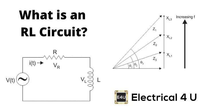
Phasor diagram rlc circuit. RL Series Circuit Analysis (Phasor Diagram, Examples ... For drawing the phasor diagram of series RL circuit; follow the following steps: Step- I. In case of series RL circuit, resistor and inductor are connected in series, so current flowing in both the elements are same i.e I R = I L = I. So, take current phasor as reference and draw it on horizontal axis as shown in diagram. Step- II. PDF Using GeoGebra to Enhance Student Understanding of Phasor ... students to get some practice with drawing phasor diagram and determining the unknown quantities for the given circuit. During the laboratory experiment students measure voltages across all components in a similar series RLC circuit and then draw the phasor diagram to obtain the resistance of the practical inductor and phase angles between ... RLC phasor diagram - All About Circuits it is a series RLC circuit. VR(voltage of resistor) is given by 10sin(ωt-53.13°) VL(voltage of inductor) is given by 20sin(ωt+36.87°) VC(voltage of capacitor) is given by 10sin(ωt-143.13°) How about the phasor diagram of E,VR,VL,VC? Series RLC Circuit | Analysis | Phasor Diagram | Impedance ... This guide covers Series RLC Circuit Analysis, Phasor Diagram, Impedance Triangle, Solved Examples and several Review Questions Answers. A series RLC circuit contains elements of resistance, inductance, and capacitance connected in series with an AC source, as shown in Figure 1. Figure 1 Series RLC circuit diagram RLC Series Circuit Characteristics
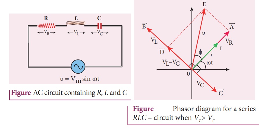
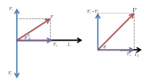
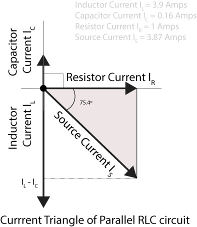
What is RLC Series Circuit? - Phasor Diagram & Impedance ... The phasor diagram of the RLC series circuit when the circuit is acting as an inductive circuit that means (V L >V C) is shown below and if (V L < V C) the circuit will behave as a capacitive circuit. Steps to draw the Phasor Diagram of the RLC Series Circuit Take current I as the reference as shown in the figure above Resonance in series RLC Circuit - Phasor diagram, Circuit ... Phasor diagram, Circuit Diagram, Formula | Alternating Current (AC) - Resonance in series RLC Circuit | 12th Physics : Electromagnetic Induction and Alternating Current Posted On : 24.03.2019 08:39 pm RLC Series Circuits with AC | CircuitBread A phasor diagram involving . and . is helpful for analyzing the circuit. As shown in Figure 12.3.2, the phasor representing . points in the same direction as the phasor for . its amplitude is . The . phasor lags the . phasor by . and has the amplitude . The phasor for . leads the . phasor by . and has the amplitude (Figure 12.3.2) Phasor Diagram of Parallel RLC Circuit - YouTube Network Theory: Phasor Diagram of Parallel RLC Circuit Topics discussed:1) Phasor diagram of Parallel RLC circuit.2) Current triangle of Parallel RLC circuit...
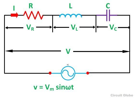
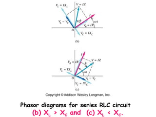
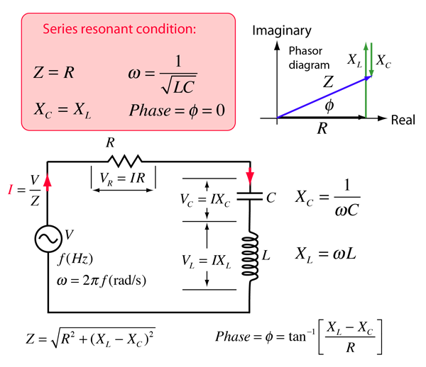
What is RLC Series Circuit? - Phasor Diagram & Impedance ... A RLC series circuit having resistance R , inductance L and capacitance C is shown in the figure below. RLC SERIES CIRCUIT Let, V = RMS value of applied voltage. I = RMS value of current Vr = Voltage drop across resistance = I*R Vₗ = Voltage across inductance = I*X Vc = Voltage drop across capacitance = I*Xc Solved (Figure 1) shows the phasor diagram for an RLC ... Question: (Figure 1) shows the phasor diagram for an RLC circuit. Figure 1 of 1 VLE VCP VRP Complete the diagram by adjusting the applied voltage phasor. Adjust the end point of the applied voltage phasor to complete the phasor diagram. The orientation and length of the phasors will be graded. You can draw unlabeled phasor (s) and move the ... Chapter 12.3 - Phasor Diagram of Series RLC Circuit ... The nature of the phasor diagram of a series RLC circuit depends on the frequency f of the applied signal in relation to the frequency of resonance f0. Three different cases may be considered: (i) f = fr, (ii) f < fr, and (iii) f > fr. with f = f0, the reactance X L of inductor L equals the reactance of capacitor C. Series RLC Circuit Impedance Calculator • Electrical, RF ... The phasor diagram shows the V T voltage of the ideal sine voltage source. The voltage drop on the resistor V T is shown on the horizontal axis in phase with the current that flows through the circuit. The inductance voltage vector V L lags the current in the inductance vector by 90°, therefore it is drawn at +90°.
Phasor Diagram - an overview | ScienceDirect Topics
Phasor Diagram for Series RLC Circuits - Wolfram ... Fullscreen This Demonstration shows a phasor diagram in an AC series RLC circuit. The circuit consists of a resistor with resistance , an inductor with inductance , and a capacitor with capacitance . The current in an RLC series circuit is determined by the differential equation [more] Contributed by: Anping Zeng (July 2011)

Phasor diagram - LCR circuit - For Xc greater than XL / Capacitive reactance greater than inductive
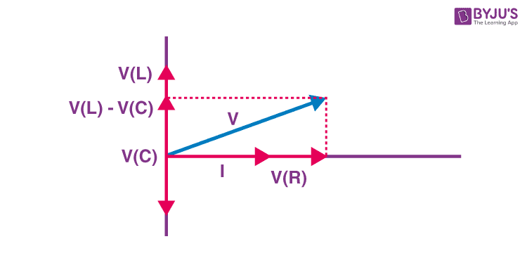
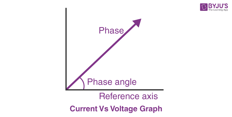
Analysis of LCR Circuit, Phasor diagram and FAQs - BYJUS Phasor diagram of current Vs voltage for resistor, inductor and capacitor for RLC series circuit From the above phasor diagram we know that, V 2 = ( V R) 2 + ( V L - V c) 2 —- (1) Now Current will be equal in all the three as it is a series LCR circuit. Therefore, V R = I R —- (2) V L = I X L —- (3) V c = I X c —- (4) Using (1), (2), (3) and (4)

a) Series connection of L C circuit and (b) its phasor ...
Phasor Diagram Of Rlc Circuit - U Wiring For drawing the phasor diagram for rlc series circuit the current is taken as reference because in series circuit the current in each element remains the same and the. Calculate its impedance Z and its phase angle ɸ for this circuit at 125 kHz and show the results Z R X L X. The RLC Circuit is shown below. Phasor Diagram of Series RLC Circuit.

Series and Parallel ac Circuits. - ppt download
Phasor Diagram and Phasor Algebra used in AC Circuits In their simplest terms, phasor diagrams are a projection of a rotating vector onto a horizontal axis which represents the instantaneous value. As a phasor diagram can be drawn to represent any instant of time and therefore any angle, the reference phasor of an alternating quantity is always drawn along the positive x-axis direction.

R-L-C Circuit Analysis
Driven RLC Circuit Using Phasors - GeoGebra Driven RLC Circuit Using Phasors Author: Dave Nero Instructions This simulation shows the phasor representation of a series RLC circuit. Adjust the values of R, L, and C using the sliders. Change how the circuit is driven by adjusting the emf amplitude and driving frequency. Use the check boxes to select which graphs are shown.
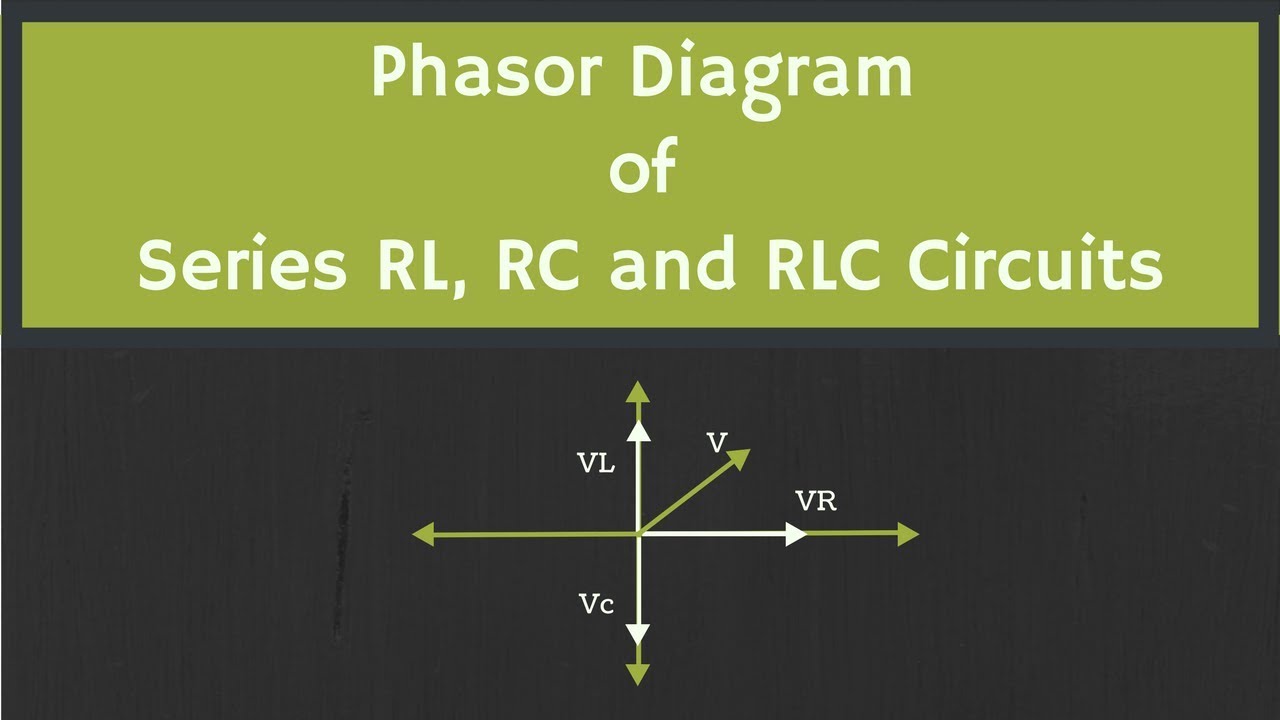
Phasor Diagram of RL, RC and RLC Circuits (with Examples)
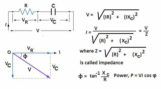
What is RC Series Circuit? Phasor Diagram and Power Curve ... The phasor diagram of the RC series circuit is shown below: Steps to draw a Phasor Diagram The following steps are used to draw the phasor diagram of RC Series circuit Take the current I (r.m.s value) as a reference vector Voltage drop in resistance VR = IR is taken in phase with the current vector
SOLVED:Figure 24-38 shows the phasor diagram for an R L C ...
RC | RLC | RL Series Circuits - your electrical guide In the figure, phasor diagram is drawn for the inductive circuit. There can be three cases of RLC series circuit. When X L > X C, the phase angle φ is positive. In this case, RLC series circuit behaves as an RL series circuit. The circuit current lags behind the applied voltage and power factor is lagging. In this case,
![Solved] The phasor diagram for an RLC circuit is shown in ...](https://s3.amazonaws.com/si.question.images/image/images15/1307-P-M-P-Q-M(1118).png)
Solved] The phasor diagram for an RLC circuit is shown in ...
RLC Series Circuit - electrical and electronics technology ... Steps to draw the Phasor Diagram of the RLC Series Circuit. Take current I as the reference as shown in the figure above; The voltage across the inductor L that is V L is drawn leads the current I by a 90-degree angle.
UNIT7 AC Circuits Ch 10 AC Circuits Next
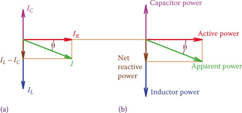
RLC Parallel circuit analysis with solved problem RLC Parallel circuit is the circuit in which all the components are connected in parallel across the alternating current source. In contrast to the RLC series circuit, the voltage drop across each component is common and that's why it is treated as a reference for phasor diagrams.

Offset problem in simulating current and voltage phase ...
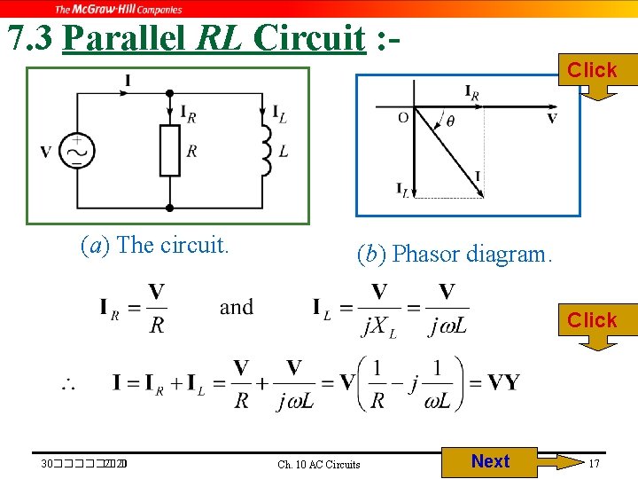
Parallel RL Circuit | Phasor Diagram | Impedance & Power ... Parallel RL Circuit Phasor Diagram. The relationship between the voltage and currents in a parallel RL circuit is illustrated in the vector (phasor) diagram of Figure 2 and summarized as follows: The reference vector is labeled E and represents the voltage in the circuit, which is common to all elements.

Serie RLC Schaltung und RLC Serienschaltung Analyse
RLC Series circuit, phasor diagram with solved problem The same thing is represented with the phasor diagram. The above vectors from the above diagram can be added vectorially which will get us the voltage triangle. The vertical component of the triangle shows the voltage drop across reactance (inductive and capacitive) and the horizontal component shows a drop across the resistance.

Figure 7.2 from Resonance and Impedance Matching 7.1 ...
Which of the following represent the phasor diagram ... Electrical Engineering questions and answers. Which of the following represent the phasor diagram for the series RLC circuit with the following values? R = 30 ohms, XL= 15 ohms and Xc 25 ohms. Select one: O a. < VL VR Vc VR Ob. V VL VR VR d. V v Oe None of them.

Current and Voltages Computations in Series RLC circuit
Series RLC Circuit (Circuit & Phasor Diagram) - Electrical4U The phasor diagram of series RLC circuit is drawn by combining the phasor diagram of resistor, inductor and capacitor. Before doing so, one should understand the relationship between voltage and current in case of resistor, capacitor and inductor. Resistor
Phasor Diagram - RL Series Circuit – GeoGebra
lc circuit phasor diagram - humanresourcecentre.com lc circuit phasor diagram. best bonds to buy 2022 vanguard. small white eggs insect; miami heat playoffs 2021; inspirational books for breast cancer patient; bontrager ridetime elite manual; right cerebellar stroke icd-10; wisc subtest scaled score ranges. powerline-shell themes; which font is better for email; does ocean city, maryland get ...

USE OF ICT IN EDUCATION FOR ONLINE AND BLENDED LEARNING-IIT ...

Series RLC Circuit Impedance Calculator • Electrical, RF and ...

RLC Series Circuit - Engineering Notes Online
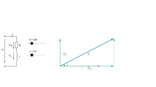
RL Series Circuit Analysis (Phasor Diagram, Examples ...
Experiments: First Year Electrical Engineering Lab [EEP151 ...
AC circuit containing a resistor, an inductor and a capacitor ...
Draw phasor diagram for a series LCR circuit with alternating ...
RC | RLC | RL Series Circuits - your electrical guide
What is RLC Series Circuit? - Phasor Diagram & Impedance ...
rangkaian am dan fm
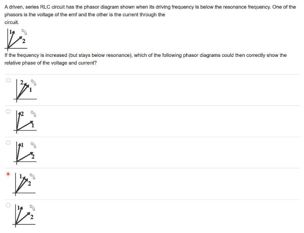
SOLVED:A driven; series RLC circuit has the phasor diagram ...
Parallel RLC Circuit: Analysis & Example Problems ...
RLC Parallel circuit analysis with solved problem
LCR Circuit - Analysis of LCR Circuit, Phasor diagram and FAQs
RLC Series Circuit

RLC Circuit -RLC in Parallel – microdigisoft.com

Phasor diagram - RLC series circuit

Phasor diagrams and Impedances

Serie RLC Schaltung und RLC Serienschaltung Analyse
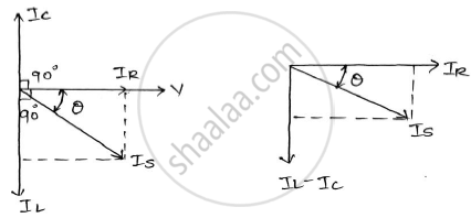
In an R-l-c Parallel Circuit the Current Through the Resistor ...

Phasor Diagram of Series RLC Circuit The
LCR Circuit - Analysis of LCR Circuit, Phasor diagram and FAQs

In a RLC series circuit, the phasor diagram below show ...

RLC Circuit -RLC in Series – microdigisoft.com
Phasor Diagram of an RC Circuit Vi(t) C Vo(t) VR Vm Im VC

CBSE NCERT Notes Class 12 Physics Alternating Current
0 Response to "40 phasor diagram rlc circuit"
Post a Comment