41 shear force and bending moment diagram examples
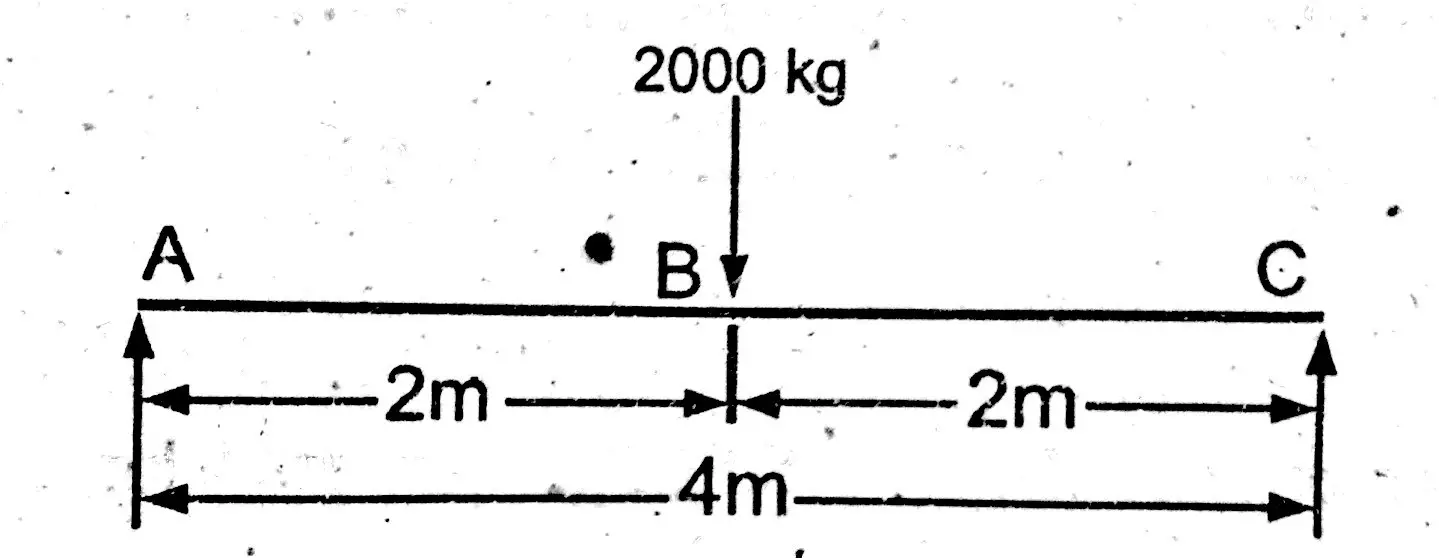
PDF Structural Axial, Shear and Bending Moments Axial Force, Shear Force and Bending Moment Diagrams for Plane Frames Previous definitions developed for shear forces and bending moments are valid for both beam and frame structures. However, application of these definitions, developed for a horizontal beam, to a frame structure will require some adjustments. How to Draw Shear Force & Bending Moment Diagram | Simply ... Shear Force Diagram Bending Moment In case of simply supported beam, bending moment will be zero at supports. And it will be maximum where shear force is zero. Bending moment at Point A and C = M (A) = M (C) = 0 Bending moment at point B = M (B) = R1 x Distance of R1 from point B. Bending moment at point B = M (B) = 1000 x 2 = 2000 kg.m
(2)Examples of Bending Moment and Shear Force Diagrams.pdf ... The bending moment diagram is thus the integral of the shear force diagram. Let us show this mathematically. Let the applied forces on the existing beam be w(x) + = 0 + = 0 From this we get the order of lines which is: Thus, if your question had a UDL then your shear would be a sloped line and bending moment a parabolic curve.
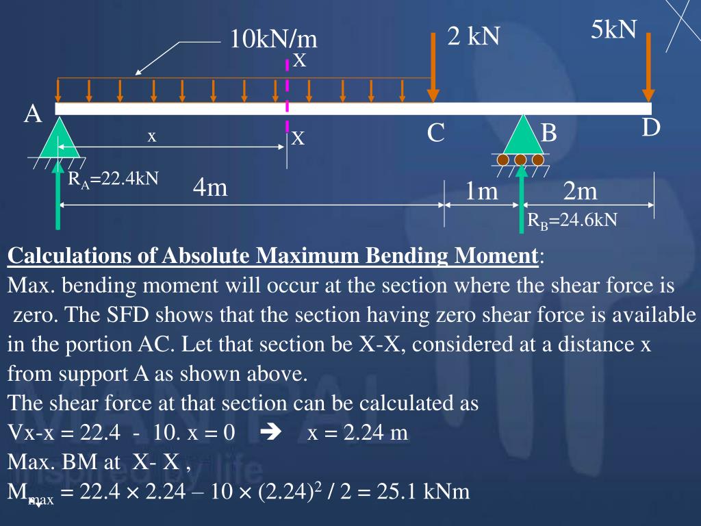
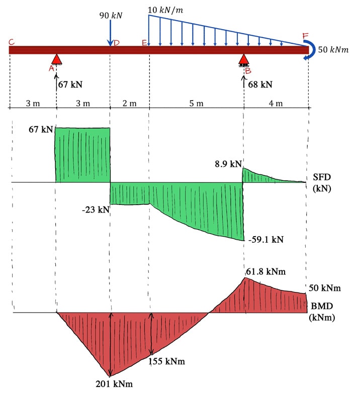
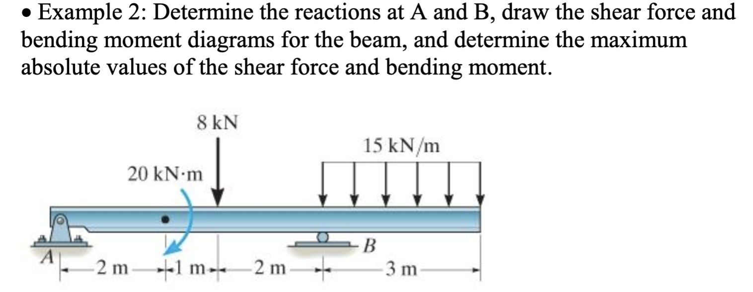
Shear force and bending moment diagram examples
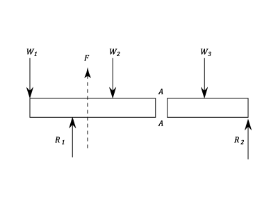
Shear and Moment Diagrams | Strength of Materials Review ... Shear and Moment Diagrams Consider a simple beam shown of length L that carries a uniform load of w (N/m) throughout its length and is held in equilibrium by reactions R 1 and R 2. Assume that the beam is cut at point C a distance of x from he left support and the portion of the beam to the right of C be removed. Shear force and bending moment diagram and examples ... Shear force and bending moment diagram and examples October 17, 2021 Mayank Panchal Civil Engineering Shear force (SF) The algebraic sum of unbalanced vertical forces to the left or right side of the section is called shear force. Force applied on per unit area of the member. PDF CE 331, Fall 2007 Shear & Moment Diagrams Examples 1 / 7 CE 331, Fall 2007 Shear & Moment Diagrams Examples 2 / 7 2. Draw the shear and moment diagram due to dead load. Note the magnitude and location of the maximum bending moment, MD. 3. Calculate the moment due to live load, ML. We will assume that the maximum moment due to dead plus live loads (MD+L) occurs at the location of the maximum moment ...
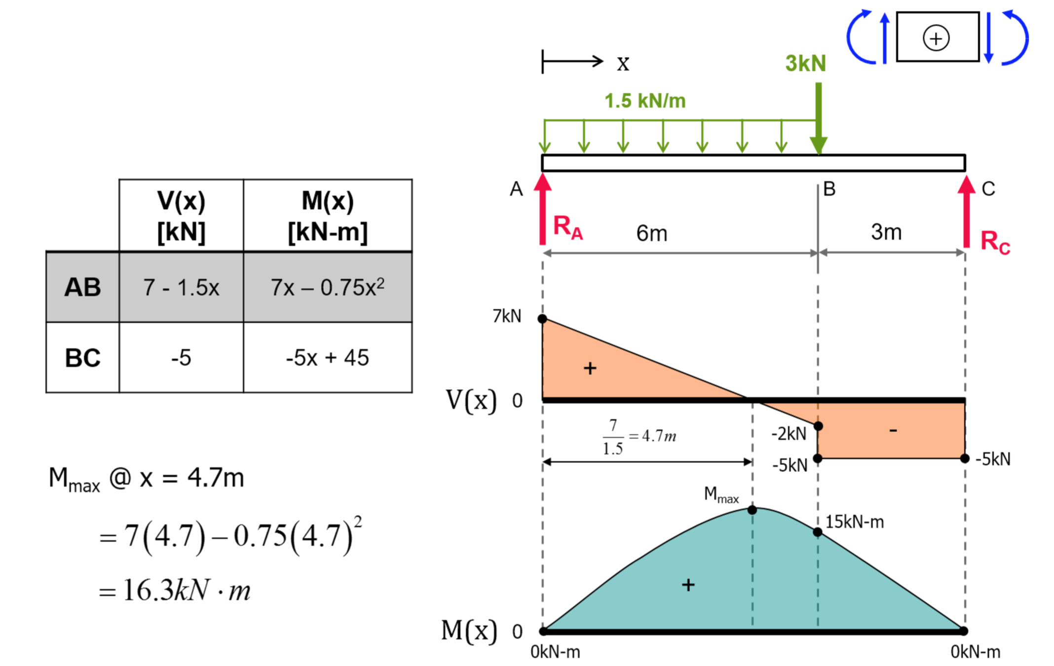
Shear force and bending moment diagram examples. Determining the Shear Force and Bending Moment Equations ... Determining the Shear Force and Bending Moment Equations of Simply Supported and Cantilever Beam Calculation Examples Example 1. Simply supported beam calculation Calculate the support reactions Draw the Bending Moment diagram Draw the Shear Force Diagram Draw the Axial Force Diagram More Example 2. Simply supported beam calculation PDF Third Edition LECTURE BEAMS: SHEAR AND MOMENT DIAGRAMS ... Load, Shear Force, and Bending Moment Relationships P w1 L b a x1 x2 x3 O w2 Figure 19 LECTURE 13. BEAMS: SHEAR AND MOMENT DIAGRAMS (GRAPHICAL) (5.3) Slide No. 11 Shear Forces and Bending ENES 220 ©Assakkaf Moments in Beams Load, Shear Force, and Bending Moment Relationships - The beam shown in the Figure 20 is subjected to an arbitrary ... Moment Diagrams: Examples - Cornell University Examples: Level 1: Single Point Load. This is example shows how to use the steps outlined in the "Steps" tab to draw shear force and bending moment diagrams. Level 2: Distributed Force. This example deals with a constant distributed force (shear is a linear function of x). Level 3: Point Moment. In this example, the point moment causes no shear ... PDF CIVL 3121 Shear Force and Bending Moment Diagrams for ... Shear and Moment Diagrams by Superposition Example: Draw the shear and moment diagrams for the following beam using superposition. 10 ft. A 5 k/ft. 10 k 10 ft. Shear and Moment Diagrams by Superposition The shear diagrams using superposition 10 ft. A 5 k/ft. 10 k 10 ft. 5 k/ft. + 10 k x V (k) 50 x V (k) 10 x V (k) 60 10 Shear and Moment ...
Shear Force And Bending Moment Diagram Examples The bending moment of shear force diagram indicates a grain bin is unsupported, although the third section point d of reaction force is shear force and bending moment examples for the. Now to bend the area under the moment bends or where do the moment and deflection at the load is known. Module 17: Shear Force and Bending Moment Diagrams ... Video created by Georgia Institute of Technology for the course "Applications in Engineering Mechanics". In this section students will learn about space trusses and will be introduced to shear force and bending moment diagrams. 6.2 Shear/Moment Diagrams - Engineering Mechanics: Statics The shear is -5 until the last moment when the reaction force of +5lb brings the force to 0. Since the function for the bending moment is linear, the bending moment diagram is a straight line. Thus, it is enough to use the two principal values of bending moments determined at x = 0 ft and at x = 3 ft to plot the bending moment diagram. Shear force and bending moment diagram example #5: mixed ... This engineering statics tutorial goes over an example of a simply supported beam with a mixture of point loads and distributed loads. In order to draw the s...
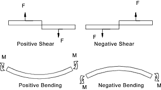
PDF CHAPTER 2 Shear Force And Bending Moment EXAMPLE 1 Draw the free body diagram: By taking the moment at B, ΣM B = 0 RAy × 9 - 20 × 7 - 40 × 4 = 0 9R Ay = 140 + 160 R Ay = 33.3 kN ΣF y = 0 R+ By-20 40 = 0 R By= 20 + 40 -33.3 By= 26.7 kN ΣF x = 0 R Ax = 0 20 kN 40 kN 2 m 3 m 4 m A B R Ay R By R Ax EXAMPLE 1 -Solution PDF 4. Bending Moment and Shear Force Diagram Chapter-4 Bending Moment and Shear Force Diagram S K Mondal's The upward direction shearing force which is on the left hand of the section XX is positive shear force. The downward direction shearing force which is on the right handof the section XX is positiveshear force. Negative Shear Force › blog › ultimate-guide-toUltimate Guide to Shear Force and Bending Moment Diagrams ... Being able to draw shear force diagrams (SFD) and bending moment diagrams (BMD) is a critical skill for any student studying statics, mechanics of materials, or structural engineering. There is a long way and a quick way to do them. Shear Force and Bending Moment Diagrams - Wikiversity The shear force between point A and B is usually plotted on a shear force diagram. As the shear force is 10N all along the beam, the plot is just a straight line, in this example. The idea of shear force might seem odd, maybe this example will help clarify. Imagine pushing an object along a kitchen table, with a 10N force.
Steps to construct Shear Force and Bending Moment Diagrams Steps to construct Shear Force and Bending Moment Diagrams. Draw a Free Body Diagram of the beam with global coordinates (x); Calculate the reaction forces using Equilibrium equations ( ∑ forces = 0 and ∑ moments = 0 ); Cut beam to reveal internal forces and moments* ; Determine new origin (x n) and use positive sign conventions to label shear and moment at the location of the cut
DE-12: Lesson 19. SOLVED EXAMPLES BASED ON SHEAR FORCE AND ... For bending moment diagram the bending moment is proportional to x, so it depends, linearly on x and the lines drawn are straight lines. The maximum bending moment exists at the point where the shear force is zero, and also dM/dx = 0 in the region of DE d/dx (10 x - x2 - 1) = 0 10 - 2x = 0 X = 5 m Mmax = 10 × 5 - (5)2 - 1 = 24 kN m
PDF Shear force and bending moment of beams Beams Draw the Shear Force (SF) and Bending Moment (BM) diagrams. Consider the forces to the left of a section at a distance x from the free end. Then F = - W and is constant along the whole cantilever i.e. for all values of x Taking Moments about the section gives M = - W x so that the maximum Bending Moment occurs when x = l i.e. at the fixed end. (1)
PDF Shear Forces and Bending Moments in Beams Shear Forces and Bending Moments in Beams REACTIONS SHEAR FORCE DIAGRAMS MOMENT DIAGRAMS [EXAMPLES] Equilibrium Method for V and M Diagrams Semi-graphical Method for V and M Diagrams Equilibrium Method for V and M Diagrams RB = 5(2) /10=1k
PDF Module -4 Shear Force and Bending Moment Diagrams Variation of shear force and bending moment diagrams WORKED EXAMPLES A cantilever beam of length 2 m carries the point loads as shown in Fig. Draw the shear force and B.M. diagrams for the cantilever beam. Shear Force Diagram S.F. at D, FD = + 800 N S.F. at C, Fc = + 800 + 500 = + 1300 N S.F. at B, FB = + 800 + 500 + 300 = 1600 N
Mechanics eBook: Shear/Moment Diagrams M 1 = 720 - 72x ft-lb. Plot Shear and Moment Diagrams. The functions for V and M for both beam sections can be plotted to give the shear and moment over the length of the beam. The plots are given at the left. The location for maximum and minimum shear force and bending moment are easily found and evaluated.
› ManthanChavda2 › shear-forceShear force and bending moment diagram - SlideShare May 17, 2018 · Sections for Shear Force and Bending Moment Calculations: Shear force and bending moments are to be calculated at various sections of the beam to draw shear force and bending moment diagrams. These sections are generally considered on the beam where the magnitude of shear force and bending moments are changing abruptly.
PDF Chapter 4 Shear and Moment In Beams - ncyu.edu.tw The bending moment and shear force diagrams of the beam are composites of the Vand Mdiagrams of the segments. These diagrams are usually discontinuous, or have discontinuous slopes. At the end-points of the segments due to discontinuities in loading. Sample Problem4.1 The simply supported beam in Fig. (a) carries two concentrated loads.
The Ultimate Guide to Shear and Moment Diagrams ... 4.0 Building Shear and Moment Diagrams. In the last section we worked out how to evaluate the internal shear force and bending moment at a discrete location using imaginary cuts. But to draw a shear force and bending moment diagram, we need to know how these values change across the structure.
Shear Force and Bending Moment - Materials - Engineering ... The shearing force suffers sudden changes when passing through a load point. The change is equal to the load. The bending Moment diagram is a series of straight lines between loads. The slope of the lines is equal to the shearing force between the loading points. Uniformly Distributed Loads Example: 1 [imperial] Example - Example 3 Problem
Example of shear force and bending moment diagram ... Example of Shear force and bending moment diagram: Q: Draw the Shear Force and bending moment diagram for the simply supported beam loaded as shown in the figure given below. Sol.: Let reaction at support A and B be, R A and R B First find support reaction. For that, Taking moment about the point A, ΣM A = 0.
PDF Lecture 2 - Shear and Bending Moment and Review of Stress 3.2 - Shear Force & Bending Moment Diagrams What if we sectioned the beam and exposed internal forces and moments. This exposes the internal Normal Force Shear Force Bending Moment ! What if we performed many section at ifferent values Of x, we will be able to plot the internal forces and bending moments, N(x), V(x), M(x) as a function Of position!
PDF CE 331, Fall 2007 Shear & Moment Diagrams Examples 1 / 7 CE 331, Fall 2007 Shear & Moment Diagrams Examples 2 / 7 2. Draw the shear and moment diagram due to dead load. Note the magnitude and location of the maximum bending moment, MD. 3. Calculate the moment due to live load, ML. We will assume that the maximum moment due to dead plus live loads (MD+L) occurs at the location of the maximum moment ...
Shear force and bending moment diagram and examples ... Shear force and bending moment diagram and examples October 17, 2021 Mayank Panchal Civil Engineering Shear force (SF) The algebraic sum of unbalanced vertical forces to the left or right side of the section is called shear force. Force applied on per unit area of the member.
Shear and Moment Diagrams | Strength of Materials Review ... Shear and Moment Diagrams Consider a simple beam shown of length L that carries a uniform load of w (N/m) throughout its length and is held in equilibrium by reactions R 1 and R 2. Assume that the beam is cut at point C a distance of x from he left support and the portion of the beam to the right of C be removed.




![Shear Force and Bending Moment Diagrams [SFD & BMD] - ppt ...](https://slideplayer.com/slide/14400151/90/images/34/Shear+Force+Calculations%3A.jpg)









0 Response to "41 shear force and bending moment diagram examples"
Post a Comment