41 radar system block diagram
PDF ARDUINO BASED RADAR SYSTEM - 3Ciencias System Block Diagram: Figure 2. Block Diagram of Radar System. Figure 2 represents the system's block diagram. Here, it can be seen how the work flow in this radar system. The sensor is going to sense the obstacle and determine the angle of incident and its distance from the radar. The servo motor is constantly rotating to and fro, hence PDF Scanning Digital Radar Receiver Corporation. The objective of the system is to be able to detect a pulsed radar signal over a large frequency range. After a pulsed radar signal has been identified, the system will output the characteristics of the signal to the user. High Level Block Diagram Figure 1 is the high level system block diagram. The input, user input mode, is ...
PDF Radar Altimeters Overview of Operation, Design, and ... • Radar Altimeter Transceivers and Signals • Signal Processing • Terrain Targets and Loop Loss Calculation • Sensitivity and Dynamic Range • All block diagrams, descriptions, parameters, and characteristics provided are typical—there will always be exceptions. • While this information is meant to give a general understanding of ...

Radar system block diagram
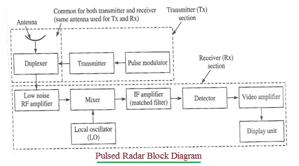
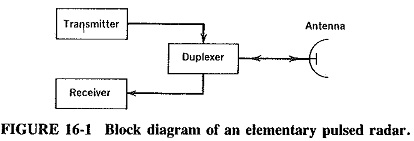
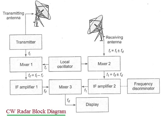
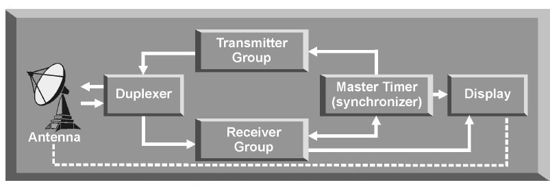
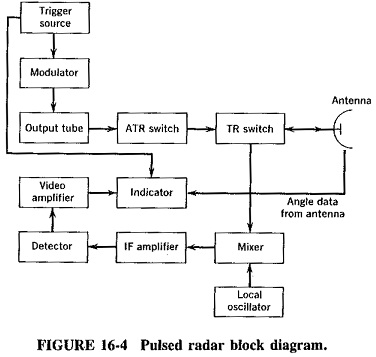
Block Diagram of RADAR Transmitter and Receiver | Download ... Contexts in source publication. Context 1. ... 4 gives results of the systems. Finally, the conclusion is mentioned in section 5. Fig.1 is block diagram of transmitter and receiver of RADAR system ... Basic Radar Block Diagram - Engineering Projects Basic Radar Block Diagram. A basic radar block diagram is shown in Fig. 1. The pulse repetition frequency is controlled by the timer (also called trigger generator or synchronizer) in the modulator block.The pulse-forming circuits in the modulator are triggered by the timer and generate high-voltage pulses of rectangular shape and short duration. PDF Basic Radar System Block Diagram: Fundamentals of Basic ... Pulsed Radar System Block Diagram: A very Pulsed Radar System Block Diagram set was shown in Figure 16-1. A more detailed block diagram will now be given, and it will then be possible to compare some of the circuits used with those treated in other contexts and to discuss in detail those circuits peculiar to radar. Block diagram and description:
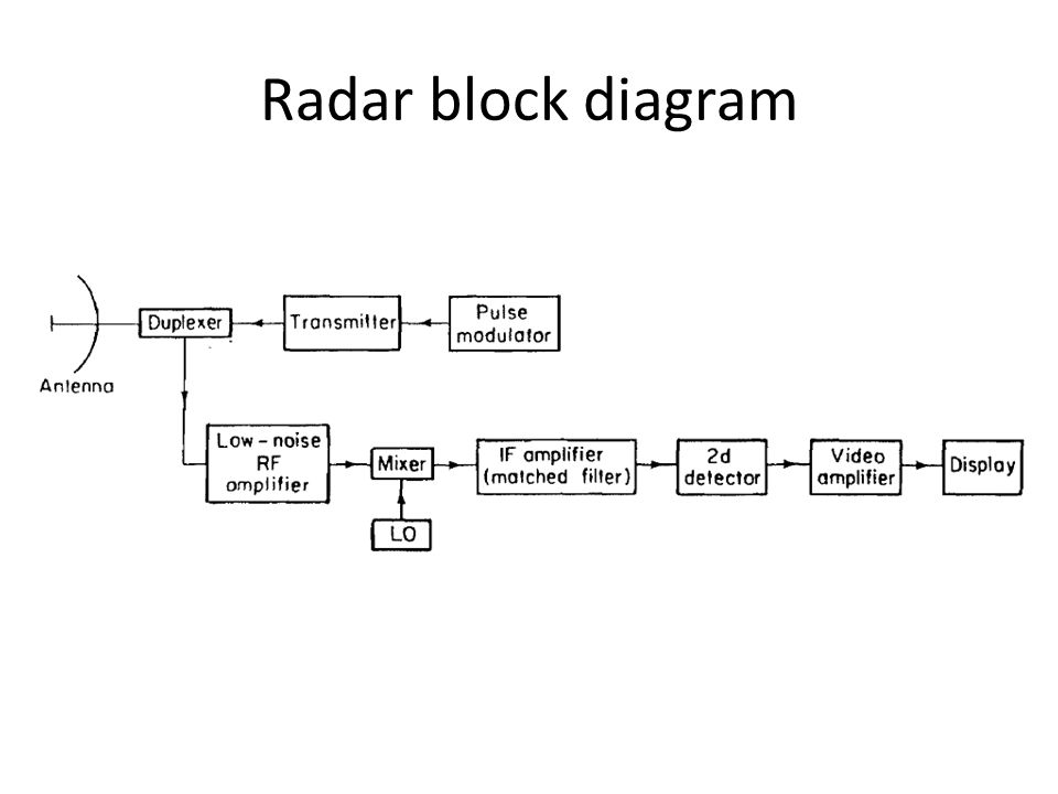
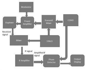
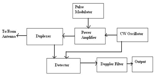
Radar system block diagram. PDF Radar Systems - Tutorialspoint RADAR is an electromagnetic based detection system that works by radiating electromagnetic waves and then studying the echo or the reflected back waves. The full form of RADAR is RA dio D etection A nd R anging. Pulse Radar system block diagram - msguide7.blogspot.com Pulse Radar system block diagram. by. - February 20, 2021 0 Comments. Pulse radar system has a rectangular pulse of high power which is used in detection and other functions. Following are the major parts of pulse radar system.-. Trigger source - The trigger source makes the pulse available to the modulator. PDF Radar Fundamentals - Naval Postgraduate School Radar Block Diagram • This receiver is a superheterodyne receiver because of the intermediate frequency (IF) amplifier. (Similar to Figure 1.4 in Skolnik.) • Coherent radar uses the same local oscillator reference for transmit and receive. PDF On Radar Systems System Losses 13 . Prediction of Range Performance • The simple form of the radar equation expressed the maximum radar range Rmax, in terms of radar and target parameters • All the parameters are to some extent under the control of the radar ... CW Radar Block Diagram
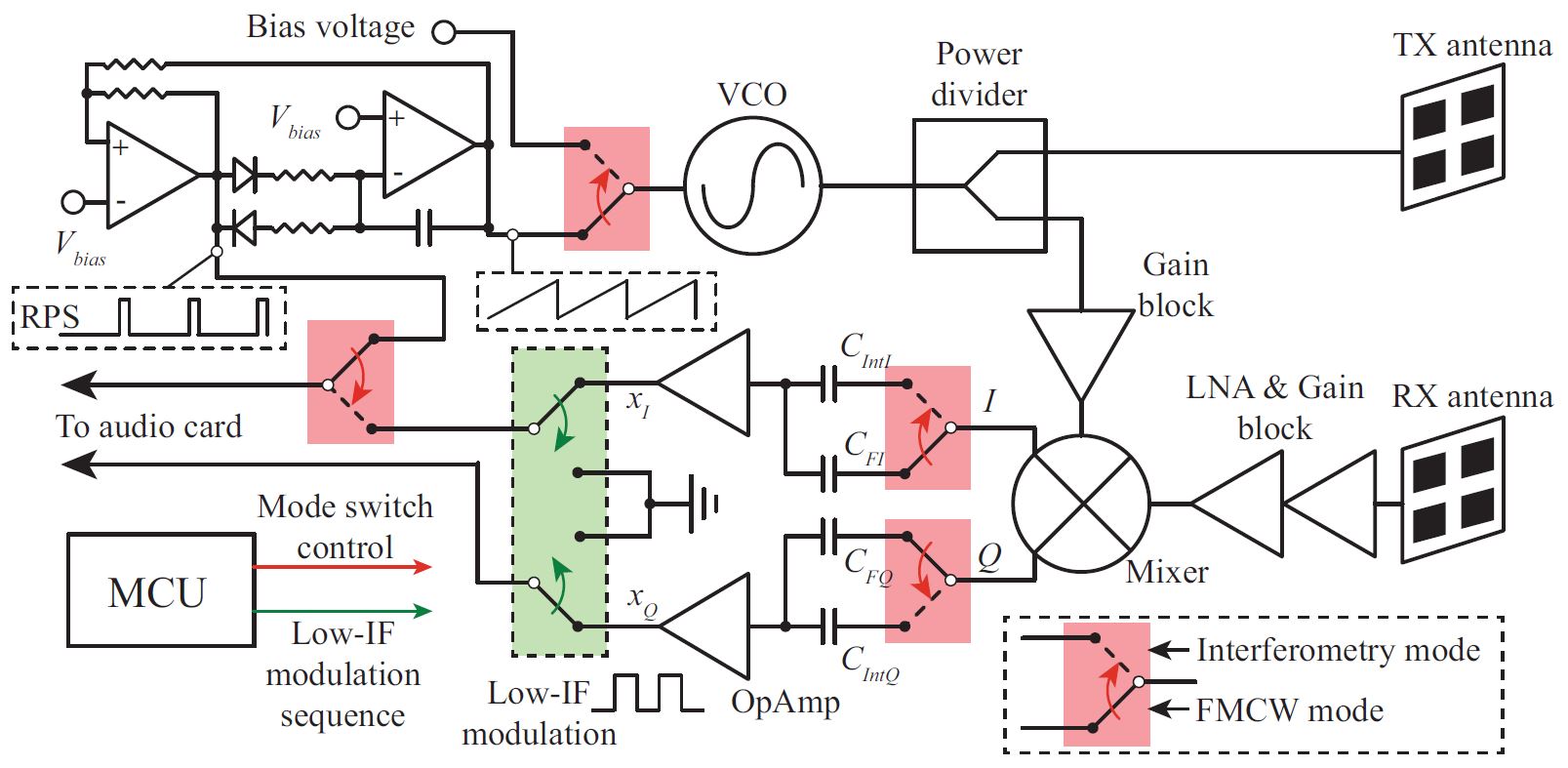
Radar Components The below figure represents a typical system for traffic radar. For multi-piece radars the antenna is usually separate from the rest of the electronics. Figure D-1-- Radar Block Diagram. Antenna GAIN Antenna gain (G) can be expressed in terms of wavelength (Lambda) and effective antenna area (A e). Effective antenna area is physical area (A ... (PDF) A novel Smeared Synthesized LFM TC-OLA Radar System ... Block diagram of SSLFM TC-OLA radar. ... Although the proposed radar system has the same processing The entire radar system with different types of SSs is deferred gain as TC-OLA-based LFM radar system, it enjoys a higher to the next paper. Table IV presents the parameters used in the spectrum spread which increases the radar immunity against ... PDF Detection and Measurement of Radar Signals: A Tutorial SYSTEM INPUT ATTENUATION FOR RSEC MEASUREMENTS B.1 Hardline Coupling to a Radar Transmitter For hardline-coupled measurements, some attenuation will likely be required between the directional coupler output and the measurement device input (see Figure 1). Referring to this diagram, the minimum decibel amount of attenuation, A, required will be: What is Radar System? Definition, Basic Principle, Block ... Content: Radar System. History; Principle; Block Diagram; Applications; History. Radar was invented for military purpose before world war II in order to secretly detect the presence of unknown objects. Initially, the transmitting tubes were not that much powerful thus worked at a very low frequency of about 60 MHz.. But further development in the field and use of magnetrons has extended the ...
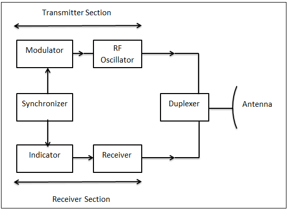
PDF Electronic Warfare Digital Radar Receiver - Bradley The sub-level block diagram shown in Figure 3 displays the EW digital radar receiver in more detail than Figure 1. Block 1 mixes an analog RF signal with an analog LO frequency from Block 2 to produce an analog intermediate frequency (IF). The IF signal is sampled by Block 3 to be processed by Block 4. In addition, Block 4 controls the LO ... What is AESA Radar | AESA Radar Block Diagram operation The figure depicts AESA radar block diagram. This type of radar houses both analog beamforming as well as digital beamforming elements. The array of antenna elements are used in AESA radar. Here both phase and amplitude of the input signal are controlled before being applied to individual antenna elements. Hence beam can be steered both in ... Basic Radar Systems Basic radar block diagram. Synchronizer. The heart of the radar system is the ,synchronizer. It generates all the necessary timing pulses (triggers) that start the transmitter, indicator sweep circuits, and ranging circuits. The synchronizer may be classified as either self-synchronized or externally synchronized. In a self-synchronized system ... Radar System - GeminiGuide.com Rendezvous Radar System Block Diagram. TRANSPONDER ANTENNA. The transponder utilizes two antenna systems, (Figure Below) a dipole antenna array and two dual spiral antennas. The selected antenna system is connected to the transponder by an antenna select switch. The dipole antenna array is located on an extendable boom which is retracted until ...
Basic block diagram of a radar system | Download Scientific ...
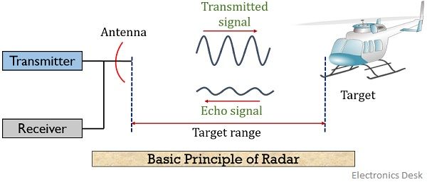
Radar Working Principle - your electrical guide Hi friends, In this article, I am discussing the radar working principle, block diagram and applications.So keep reading. A radar which stands for "radio detection and ranging" is a method of detecting the presence and position of objects by reflected radio waves. The detected object is called target and the distance to the target is determined by measuring the time interval between ...

General block diagram of the radar system. | Download ...
PDF Radar Transmitter/Receiver - MIT Lincoln Laboratory Radar range equation for search (S/N = signal to noise ratio) • S/N of target can be enhanced by - Higher transmitted power P. av - Lower system losses L - Minimize system temperature T. s. R k T L P A t S/N . s 4 av e s. Ω = 4π σ. The design of radar transmitter/receiver affects these three parameters directly. P. av = average power ...
Doppler Block Diagram
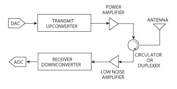
PDF RADAR SYSTEM BLOCK DIAGRAM LO - Pasternack RADAR SYSTEM BLOCK DIAGRAM . Circulator Receiver Protector Synchronous I/ Q Detector ADC and Signal Processor Display Pulse Generator Mixer Mixer Coupler Coupler Oscillator LO PA Radar LNA. ISO 9001 : 2008 Registered Pasternack Enterprises, Inc. P.o. Box 16759, Irvine, CA 92623 Phone: (866) 727-8376 or (949) 261-1920 Fax: (949) 261-7451
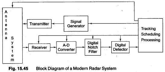
Block Diagram of a Modern Radar Systems Analysis
UWB Radar Tutorial | UWB Radar System working Block diagram UWB Radar working operation. The radar system which uses signal having UWB characteristics is known as UWB radar. The UWB signal occupies much wider frequency compare to conventional radar system. Moreover it uses very low power which is less than thermal noise signal power. The figure depicts typical UWB transmitter and receiver block diagram.
Advantages of Pulsed Radar | disadvantages of Pulsed Radar
PDF Radar Systems Engineering Lecture 17 Transmitters & Receivers Simplified Radar Transmitter/Receiver System Block Diagram. Receiver. LNA. Filter. A/D. Coverters. HPA. Filter. Duplexer. Waveform. Generator. High Power Transmit Sections (~100 W to ~MW) Low Power Transmit Section (~100mw to ~1W) • Radar transmitter and receiver can be divided into two major subsystems: - Low power transmit and receive ...

ECE 41 RADAR SYSTEMS I RADAR BLOCK DIAGRAM I - YouTube
Radar Block Diagram and Working Principle - Electronics ... Block Diagram of Radar: The transmitter can be a power amplifier such as klystron, travelling wave tube etc. It can also be a power oscillator such as magnetron. The radar signal is produced at low power by a waveform generator which is then amplified by the power amplifier. The output of the power amplifier is delivered to the antenna by a ...

Figure 2 from Lesson 4. Track Radar Systems | Semantic Scholar
Block Diagrams for RF and Microwave Systems - Pasternack Pasternack's library RF and microwave block diagram are designed to provide engineers and designers with examples of common RF systems schematics while illustrating the RF products and where they fit into the system's design. ... Radar System. Radar Chip-Set. 13.75 - 14.5 GHz VSAT Radio. 28 - 31.5 GHz VSAT Radio. 71 - 81 GHz E-Band Radio.
Pulsed Radar System Block Diagram | Types of Modulators
Universal Block Diagram of Pulse Radar - Radartutorial Figure 1: Universal Block Diagram of Pulse Radar This block diagram may be used for your own lessons but there are no block labels in the animation and there is no background image (landscape). These block labels can be placed in an own layer over the animation in e.g. MS-PowerPoint with text boxes in your own language version.
Design, System Integration and Testing of Radar Systems - NI
What is radar block diagram? | Popular Answers Basic Radar System Block Diagram consists of a transmitter and a receiver, each connected to a directional antenna. The receiver collects as much energy as possible from the echoes reflected in its direction by the target and then processes and displays this information in a suitable way.
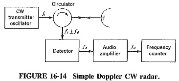
CW Doppler Radar Block Diagram | Advantages | Applications ...
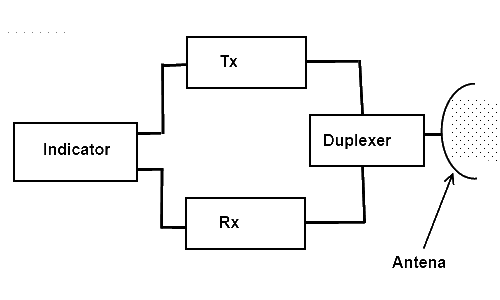
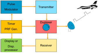
Radar Systems - Pulse Radar - Tutorialspoint Block Diagram of Pulse Radar. Pulse Radar uses single Antenna for both transmitting and receiving of signals with the help of Duplexer. Following is the block diagram of Pulse Radar −. Let us now see the function of each block of Pulse Radar −. Pulse Modulator − It produces a pulse-modulated signal and it is applied to the Transmitter.
RADAR Block Diagram (Bistatic RADAR & Monostatic RADAR)
Radar system - SlideShare The radar antenna illuminate the target with a microwave signal, which is then reflected and picked up by a receiving device and Radar signals can be displayed on the traditional plan position indicator (PPI) other more advanced radar display systems Fig.2: Block diagram of a primary radar 8.
Advantages of CW Radar | disadvantages of CW Radar
PDF Basic Radar System Block Diagram: Fundamentals of Basic ... Pulsed Radar System Block Diagram: A very Pulsed Radar System Block Diagram set was shown in Figure 16-1. A more detailed block diagram will now be given, and it will then be possible to compare some of the circuits used with those treated in other contexts and to discuss in detail those circuits peculiar to radar. Block diagram and description:
RADAR | Electronic tutorial | Mepits | Mepits
Basic Radar Block Diagram - Engineering Projects Basic Radar Block Diagram. A basic radar block diagram is shown in Fig. 1. The pulse repetition frequency is controlled by the timer (also called trigger generator or synchronizer) in the modulator block.The pulse-forming circuits in the modulator are triggered by the timer and generate high-voltage pulses of rectangular shape and short duration.

Moving Target Indicator (MTI) Radar
Block Diagram of RADAR Transmitter and Receiver | Download ... Contexts in source publication. Context 1. ... 4 gives results of the systems. Finally, the conclusion is mentioned in section 5. Fig.1 is block diagram of transmitter and receiver of RADAR system ...

Radar Principle - Radartutorial
Sensors | Free Full-Text | A Review on Low-Cost Microwave ...
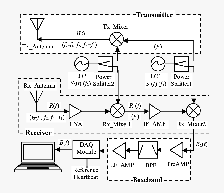
System Block Diagram Of Ka-band Heartbeat Detector - Radar ...
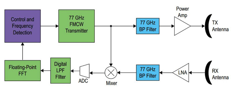
The Radar Technology Behind Autonomous Vehicles - Electrical ...
Lecture Notes On
What is Radar System? Definition, Basic Principle, Block ...
Keysight Technologies UK - New facelift for radar – but the ...
Electronic Warfare - Radar System - Full Afterburner
C-Band Portable Multi-Mode Radar – Z. PENG

Sensors | Free Full-Text | Portable Microwave Radar Systems ...
RADAR system References: Intoduction to Radar Systems Merill ...

Weather radar system basics | Applications,scanning techniques
RADAR - Basics, Types, Working, Range Equation & Its Applications
RADAR
Basic block diagram of RADAR Communication [1] | Download ...

Universal Block Diagram of Pulse Radar - Radartutorial

Figure 1.1 from CHAPTER 1 AN INTRODUCTION TO RADAR | Semantic ...
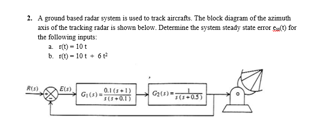
Solved 2. A ground based radar system is used to track ...
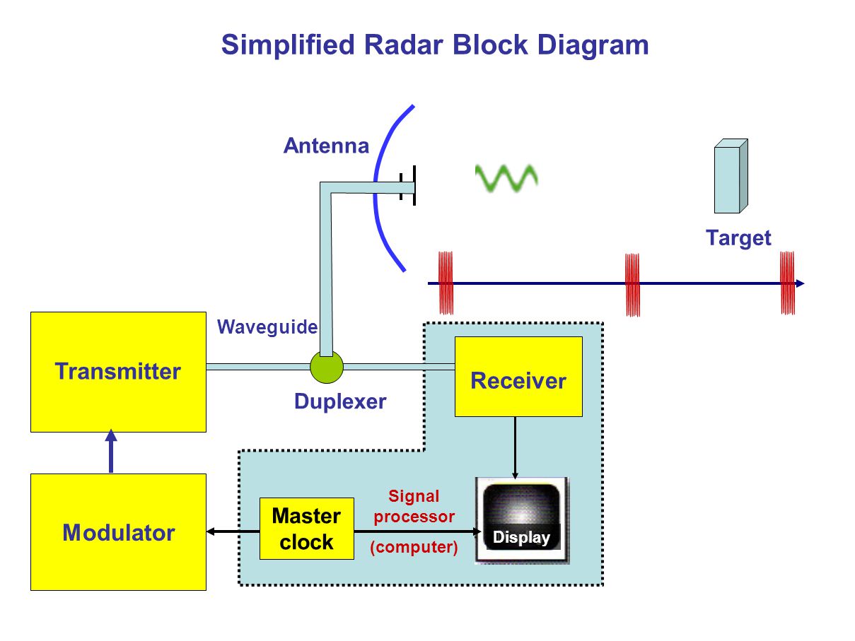
Simplified Radar Block Diagram - ppt download

Radartutorial
RADAR - Basics, Types, Working, Range Equation & Its Applications
/Year_5/ELC-544E-Radar%20Systems%20and%20Satellite/RADAR/Images/Radar%20Block_Diagram(1).GIF)
Introduction to Radar Systems

Figure 10.1 from 0 Pulse Compression 10.1.1 Block Diagram ...
Pulsed Radar System Block Diagram | Types of Modulators

Radar Block Diagram and Working Principle - Electronics and ...
Wideband Radar System Testing - Electronics Maker
Basic Radar System Block Diagram: Fundamentals of Basic Radar ...
0 Response to "41 radar system block diagram"
Post a Comment