41 each class on an class diagram is represented by a(n) ____ in a relational database.
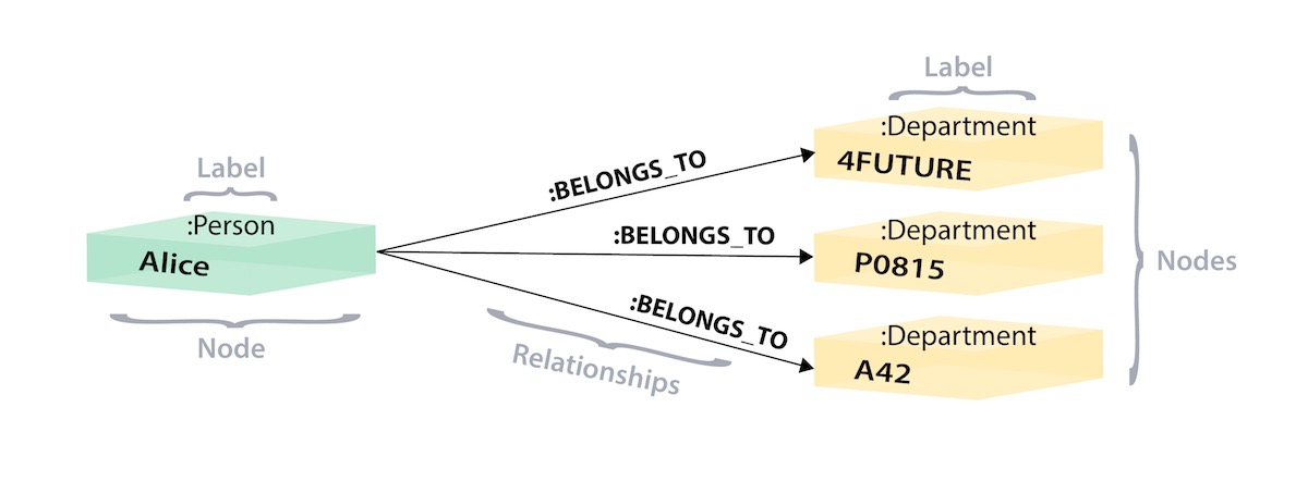
Info 311-Chapter 9 Flashcards - Quizlet A relational database table is in ____ normal form if every non-key field is functionally dependent on the primary key. ... ____ is a field or set of fields used to uniquely identify each row. ... Each class on an class diagram is represented by a(n) ____ in a relational database. ... Three Table Types Relationship(1:1, 1:n, m:n) There are three types of relationships that can exist between two entities. An entity-relationship (ER) diagram can be created based on these three types, which are listed below: one-to-one relationship: In relational database design, a one-to-one (1:1) relationship exists when zero or one instance of entity A can be associated with zero or one ...
SAD Designing Database | Computers Quiz - Quizizz 10 Questions Show answers. A (n) ____ describes the structure, content, and access controls of a physical data store or database. (n) ____ is a field or set of fields used to uniquely identify each row. Each class on an class diagram is represented by a (n) ____ in a relational database. Referential integrity is normally enforced by the ____.
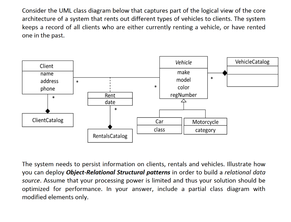
Each class on an class diagram is represented by a(n) ____ in a relational database.
An event that occurs by reaching a point in time is called ... Each class on an class diagram is represented by a(n) _____ in a relational database. A. attribute B. row C. table D. column. C. table. 19. A(n) _____ is a field or set of fields used to uniquely identify each row in a database table. A. primary key B. foreign key C. object identifier D. Attribute. Chapter 6+7+9, System Analysis and Design - Chapter 7 ... Each class on an class diagram is represented by a(n) ____ in a relational database. table In a one-to-many association the primary key of the "many" class is placed as a foreign key in the "one" class. Class Diagram Relationships in UML Explained with Examples A class diagram is a collection of classes similar to the one above. Relationships in Class Diagrams. Classes are interrelated to each other in specific ways. In particular, relationships in class diagrams include different types of logical connections. The following are such types of logical connections that are possible in UML: Association
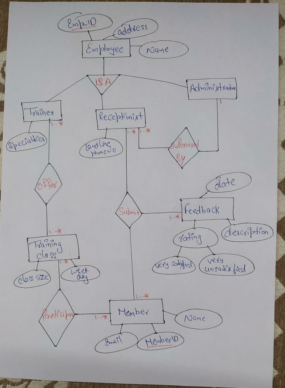
Each class on an class diagram is represented by a(n) ____ in a relational database.. Completeness control is an integrity control that ... A(n) ____ is a field or set of fields stored in one table that also exists as a primary key in another table. a. primary key c. object identifier b. foreign key d. column ANS: B PTS: 1 REF: p375 9. Each class on an class diagram is represented by a(n) ____ in a relational database. a. attribute c. table b. row d. column ANS: C PTS: 1 REF: p377 10. Converting an E-R diagram to a relational schema - Piazza Converting an E-R diagram to a relational schema Below describes a mechanical procedure for converting an E-R diagram to a relational schema. We will use the student-section-course database as an example: 1. (non-weak) Entity sets. Create a relation for each entity set. It can use the same name and same set of attributes as the entity set. ISYS 3293 Quizzes for Final Flashcards | Quizlet Each class on an class diagram is represented by a(n) ____ in a relational database. table A(n) ____ is a field or set of fields used to uniquely identify each row. What is Entity Relationship Diagram (ERD)? - Visual Paradigm Entity Relationship Diagram, also known as ERD, ER Diagram or ER model, is a type of structural diagram for use in database design. An ERD contains different symbols and connectors that visualize two important information: The major entities within the system scope , and the inter-relationships among these entities .
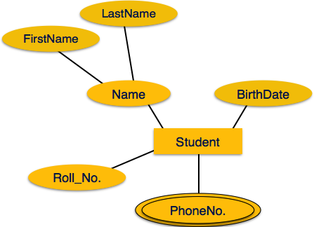
ER Diagram: Entity Relationship Diagram Model | DBMS Example ER Model in DBMS stands for an Entity-Relationship model. The ER model is a high-level data model diagram. ER diagrams are a visual tool which is helpful to represent the ER model. ER diagrams in DBMS are blueprint of a database. Entity relationship diagram DBMS displays the relationships of entity set stored in a database. How to Convert ER Diagram to Relational Database | Learn ... The ER diagram represents the conceptual level of database design meanwhile the relational schema is the logical level for the database design. We will be following the simple rules: 1. Entities and Simple Attributes: An entity type within ER diagram is turned into a table. Class Diagram | Types & Examples - EDUCBA The class diagram is one of the types of UML diagrams which is used to represent the static diagram by mapping the structure of the systems using classes, attributes, relations, and operations between the various objects. A class diagram has various classes; each has three-part; the first partition contains a Class name which is the name of the ... Data Modeling and Entity Relationship Diagram (ERD) Data Modeling. Data modeling is a technique to document a software system using diagrams and symbols. It is used to represent communication of data. The highest level of abstraction for the data model is called the Entity Relationship Diagram (ERD). It is a graphical representation of data requirements for a database.
597- Ch 12 Flashcards - Quizlet Each class on an class diagram is represented by a(n) ____ in a relational database. table. What is the name of the control mechanism that is used to ensure that all necessary information for a transaction has been entered? completeness control. Ch. 9 Flashcards - Quizlet A database management system A foreign key is a field or set of fields stored in one table that also exists as a primary key in another table. True Each class on an class diagram is represented by a(n) ____ in a relational database. table In a one-to-many association the primary key of the "many" class is placed as a foreign key in the "one" class. Database Design - Many-to-many There is a fourth type, the many-to-one relationship, however, that is just the reverse direction of the one-to-many relationship. This article introduces a design pattern for the many-to-many relationship, and shows the UML class diagram which is then mapped to the relational model. The sales database PDF 1 Class Diagrams and Entity Relationship Diagrams (ERD) 2 ... Class diagrams and ERDs both model the structure of a system. Class diagrams represent the dynamic aspects of a system: both the structural and behavioural features. ERDs, depicting only structural features provide a static view of the system. 2 Class Diagrams 2.1 Elements of a class diagram: 2.1.1 class Class Name A class is a general concept ...
CIS201Ch12Review - CIS 201 Chapter 12 Review Test True ... (1 point) Relationships in a relational database are usually represented by embedding a foreign key in each participating table. 7. (1 point) Classes that participate in a classification hierarchy can be represented within a relational database as a set of tables with the primary key of the general class table replicated in the other tables. 8.
Chapter 8 The Entity Relationship Data Model - Database ... Class(CrsCode, Section, ClassTime…) Types of Relationships. Below are descriptions of the various types of relationships. One to many (1:M) relationship. A one to many (1:M) relationship should be the norm in any relational database design and is found in all relational database environments. For example, one department has many employees.
In a relational database a row can be referred to as an a ... In a relational database a row can be referred to as an a Field c attribute b from IDS 405 at University of Illinois, Chicago ... For each of the following relations, indicate the normal form for that relation. ... Each class on an class diagram is represented by a(n) ____ in a relational database. a. Attribute c. Table b. Row d. Column.
Relational Database Schemas: Types and Examples A database is a collection of interrelated data files or structures. A relational database schema is an arrangement of relation states in such a manner that every relational database state fulfills the integrity constraints set on a relational database schema.
The activity of a single-celled organism is represented in ... Each class on an class diagram is represented by a(n) ____ in a relational database. Refer to the diagrams. with the industry structures represented by diagram; Determine the net force acting on the object (represented by the solid circle) in this diagram. In a state machine diagram, a state is represented by a(n) _____.
Class Diagram for Library Management System - GeeksforGeeks In diagram given below, we can see that aggregation is represented by an edge with a diamond end pointing towards superclass. The "Library Management System" is superclass that consists of various classes. These classes are User, Book, and Librarian as shown in diagram. Further, for "Account" class, "User" is a superclass.
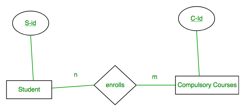
PDF Data Modeling - Texas Southern University A many to many (M:N) relationship is not supported directly in the relational environment. They are usually implemented by creating a new entity in 1:M relationships with the original entities. Example: Each CLASS is taken by many students, and each STUDENT can take many CLASSes.
Question options d vehicle Vehicle Vehicle Vehicle tion ... Question options: a attribute relation tuple element Question 9 0.25 / 0.25 points Each class on an class diagram is represented by a(n) ____ in a relational database. Question options: c attribute row table column Question 10 0.25 / 0.25 points A separate relation must be created to store the attributes of a ____ relationship among two other ...
Each class on an class diagram is represented by a(n ... A state-machine diagram is usually developed for every class in the problem domain class diagram. Refer to the diagram to the right. the firm represented in the diagram makes In a relational database, the three basic operations used to develop useful sets of data are:
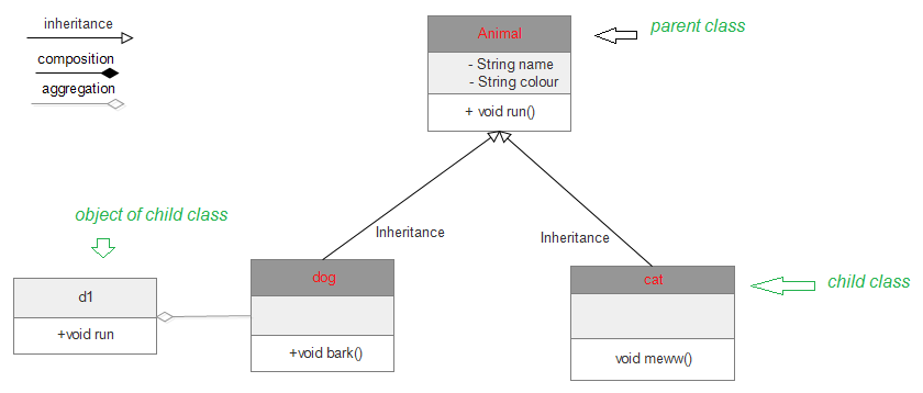
Class Diagram Relationships in UML Explained with Examples A class diagram is a collection of classes similar to the one above. Relationships in Class Diagrams. Classes are interrelated to each other in specific ways. In particular, relationships in class diagrams include different types of logical connections. The following are such types of logical connections that are possible in UML: Association
Chapter 6+7+9, System Analysis and Design - Chapter 7 ... Each class on an class diagram is represented by a(n) ____ in a relational database. table In a one-to-many association the primary key of the "many" class is placed as a foreign key in the "one" class.
An event that occurs by reaching a point in time is called ... Each class on an class diagram is represented by a(n) _____ in a relational database. A. attribute B. row C. table D. column. C. table. 19. A(n) _____ is a field or set of fields used to uniquely identify each row in a database table. A. primary key B. foreign key C. object identifier D. Attribute.




![Efficient processing of complex XSD using Hive and Spark [PeerJ]](https://dfzljdn9uc3pi.cloudfront.net/2021/cs-652/1/fig-3-full.png)






0 Response to "41 each class on an class diagram is represented by a(n) ____ in a relational database."
Post a Comment