41 bending moment diagram examples
PDF Module -4 Shear Force and Bending Moment Diagrams A bending moment (BM) is defined as the algebraic sum of the moments of all the forces either to the left or to the right of a section. Fig. 5.5. Bending moment at section Bending Moment at section x-x = Sign convention of SF and BM For Shear force: We shall remember one easy sign convention, i.e., to the right side of a section, external force PDF 4. Bending Moment and Shear Force Diagram bending moment occurs at the fixed end i.e. M max= - PL (at x = L) S.F and B.M diagram (ii) A Cantilever beam with uniformly distributed load over the whole length When a cantilever beam is subjected to a uniformly distributed load whose intensity is given w /unit length. Shear force:
Shear and moment diagram example problems with solutions ... Example 1 (Calculate the bending moment diagram,M) Draw the bending moment diagram for the simple beam below supporting a 5 Kip concentrated load, 5 ft from reaction A, as shown below. The portal method is used as an approximate in order to solve for the axial, shear, and moment diagrams for the frame shown below.

Bending moment diagram examples
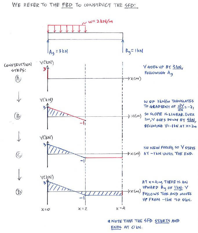
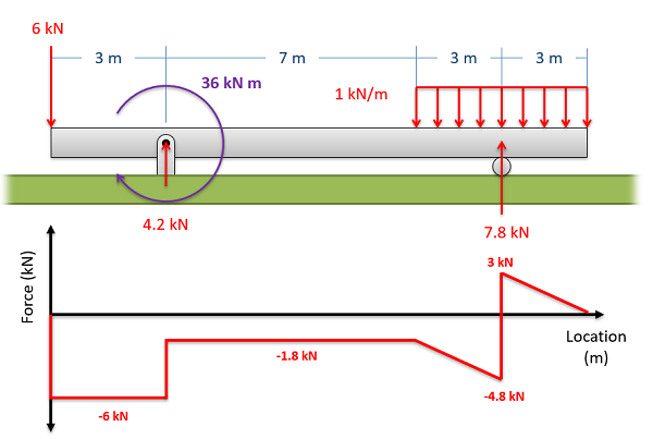
Shear force and bending moment diagram and examples ... Calculate the shear force and bending moment for the beam subjected to a concentrated load, then draw the shear force diagram (SFD) and bending moment diagram (BMD). Answer: By taking the moment at A, MA = 0 - RBy × 5 + 15 × 3 = 0 RBy = 9 kN Fy = 0 RAy + RBy = 15 RAy = 15 - 9 RAy = 6 kN Fx = 0 , RAx = 0 Shear force and bending moment diagram en.wikipedia.org › wiki › Introduction_to_generalIntroduction to general relativity - Wikipedia Notable examples of great interest to astronomers are quasars and other types of active galactic nuclei. Under the right conditions, falling matter accumulating around a black hole can lead to the formation of jets, in which focused beams of matter are flung away into space at speeds near that of light. PDF Structural Axial, Shear and Bending Moments Shear and bending moment diagrams depict the variation of these quantities along the length of the member. Proceeding from one end of the member to the other, sections are passed. After each successive change in loading along the length of the member, a FBD (Free Body Diagram) is drawn to determine the equations express-ing the shear and ...
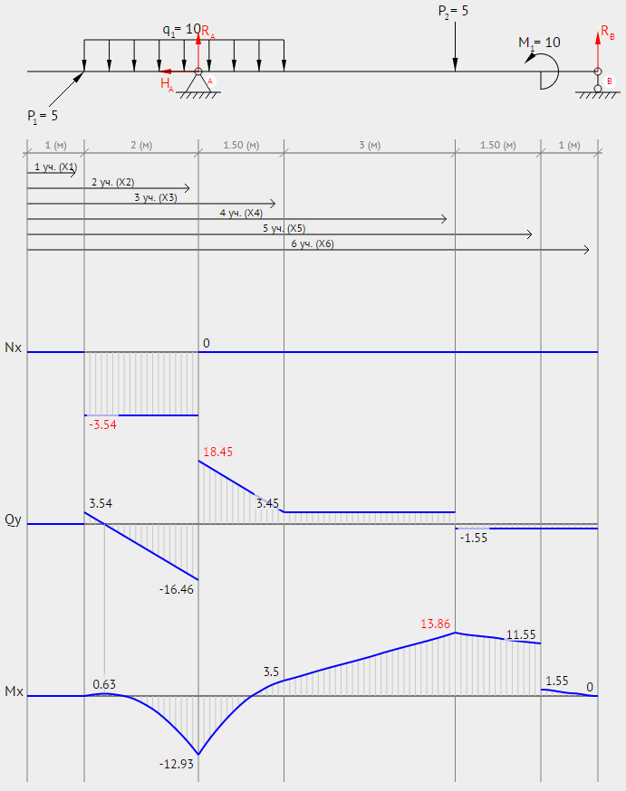
Bending moment diagram examples. Determining the Shear Force and Bending Moment Equations ... Example 2. Simply supported beam calculation. Calculate the support reactions. Draw the Bending Moment diagram. Draw the Shear Force Diagram. Draw the Axial Force Diagram. More. Example 3. Cantilever beam calculation carrying a uniformly distributed load and a concentrated load. The Ultimate Guide to Shear and Moment Diagrams ... the internal bending moment at the cut, the internal shear force at the cut, This starts to make more sense when we plug some numbers into an example. For the beam above, let's imagine it has a span m, applied loading of kN/m and imagine we cut the beam at m from the left hand support. The left hand reaction, is, (7) Shear Force and Bending Moment - Materials - Engineering ... The bending Moment diagram is a series of straight lines between loads. The slope of the lines is equal to the shearing force between the loading points. Uniformly Distributed Loads Example: 1 [imperial] Example - Example 3 Problem Ultimate Guide to Shear Force and Bending Moment Diagrams ... Shear force and bending moment diagram example #4: applied moment; Shear force and bending moment diagram example #5: mixed distributed and point loads; The Quick Way To Solve SFD & BMD Problems. Shear force and bending moment diagram practice problem #1; Shear force and bending moment diagram practice problem #2
PDF CIVL 3121 Shear Force and Bending Moment Diagrams for ... Shear and Moment Diagrams by Superposition Example: Draw the shear and moment diagrams for the following beam using superposition: + = + Shear and Moment Diagrams by Superposition Example: Draw the shear and moment diagrams for the following beam using superposition: + = + CIVL 3121 Shear Force and Bending Moment Diagrams for Frames 4/5 What is Bending Moment? | SkyCiv Engineering In the above example, the bending moment at point A is simply the distance multiplied by the force. Therefore, the Bending Moment at Point A = 0.2 (10) = 2 Nm. It is important to note that to use the above formula, the force (in this case a 10 N downward force) must NOT pass through the point. PDF Beam Diagrams and Formulas BEAM DIAGRAMS AND FORMULAS Table 3-23 (continued) Shears, Moments and Deflections 13. BEAM FIXED AT ONE END, SUPPORTED AT OTHER-CONCENTRATED LOAD AT CENTER PDF Bending Stress Example To solve for the maximum bending stress in a statically determinate, constant cross-section beam: (1) Solve for the support reactions and plot the shear diagram to arrive at the Moment Diagram. (2) From the moment diagram read off the maximum moment (negative or positive) in the beam, M max. (3) Calculate the location of the centroid of the ...
PDF Lecture 2 - Shear and Bending Moment and Review of Stress 3.2 - Shear Force & Bending Moment Diagrams What if we sectioned the beam and exposed internal forces and moments. This exposes the internal Normal Force Shear Force Bending Moment ! What if we performed many section at ifferent values Of x, we will be able to plot the internal forces and bending moments, N(x), V(x), M(x) as a function Of position! DE-12: Lesson 19. SOLVED EXAMPLES BASED ON SHEAR FORCE AND ... For bending moment diagram the bending moment is proportional to x, so it depends, linearly on x and the lines drawn are straight lines. The maximum bending moment exists at the point where the shear force is zero, and also dM/dx = 0 in the region of DE d/dx (10 x - x2 - 1) = 0 10 - 2x = 0 X = 5 m Mmax = 10 × 5 - (5)2 - 1 = 24 kN m Shear force and bending moment_solved problems ... Draw a FBD of the beam section showing and labeling all forces and toque acting - including the shear force and bending moment (which act as an external force and torque at the point where we cut the beam.) (See Diagram - Section 1) Notice we have drawn the shear force and bending moment in their positive directions according to the defined ... › pmmc-instrumentPMMC Instrument : Construction, Working & Its Applications Sep 18, 2021 · The basic PMMC instrument diagram is shown below. A rectangular coil of thin wire with some turns is wound on an aluminum frame, which has an iron core inside. It is placed between the U-shaped permanent magnet poles, which are made up of Alnico (magnetic alloy).
Shear force and bending moment diagram practice problem #1
Shear and Moment Diagrams | Strength of Materials Review ... Shear and Moment Diagrams Consider a simple beam shown of length L that carries a uniform load of w (N/m) throughout its length and is held in equilibrium by reactions R1 and R2. Assume that the beam is cut at point C a distance of x from he left support and the portion of the beam to the right of C be removed. The portion removed must then be replaced by vertical shearing
Mechanics of Materials Chapter 4 Shear and Moment In Beams
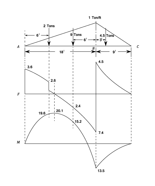
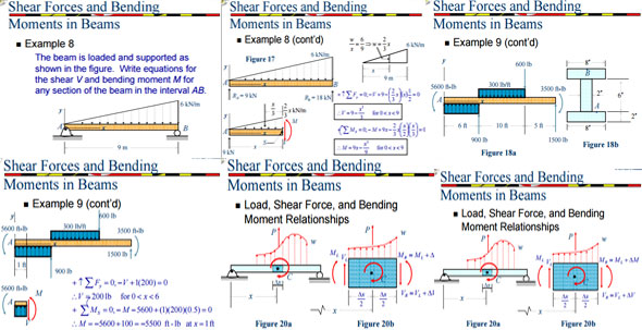
PDF Shear Forces and Bending Moments in Beams PDF_C8_b (Shear Forces and Bending Moments in Beams) Q6: A simply supported beam with a triangularly distributed downward load is shown in Fig. Calculate reaction; draw shear force diagram; find location of V=0; calculate maximum moment, and draw the moment diagram. 6k/ft 9 ft RA = (27k)(9-6)/9= 9k A B F = (0.5x6x9) = 27k x = (2/3)(9) = 6 ft
Shear and Moment Diagram Example 3 - Mechanics of Materials
Moment Diagrams: Examples - Cornell University Examples: Level 1: Single Point Load. This is example shows how to use the steps outlined in the "Steps" tab to draw shear force and bending moment diagrams. Level 2: Distributed Force. This example deals with a constant distributed force (shear is a linear function of x). Level 3: Point Moment. In this example, the point moment causes no shear ...

Structure Analysis I. Lecture 8 Internal Loading Developed in ...
What Is A Bending Moment In A Beam? The bending moment is a reaction in a structural element that is subjected to an external force or moment, causing bending. Beams are a structural element, which are associated with bending moment diagrams and analysis.. When a load is applied to the beam which is large in magnitude, failure of the beam can occur.

Shear force and bending moment diagram and examples - PIGSO ...
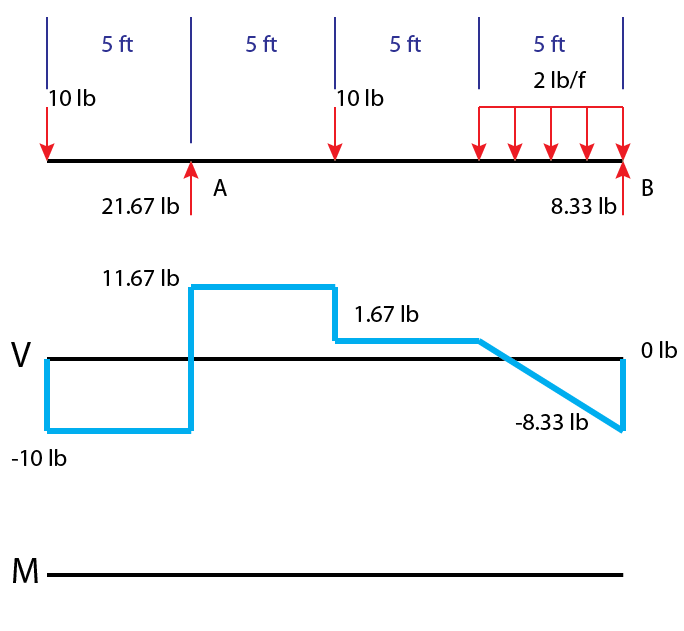
PDF CHAPTER 2 Shear Force And Bending Moment EXAMPLE 1 Draw the free body diagram: By taking the moment at B, ΣM B = 0 RAy × 9 - 20 × 7 - 40 × 4 = 0 9R Ay = 140 + 160 R Ay = 33.3 kN ΣF y = 0 R+ By-20 40 = 0 R By= 20 + 40 -33.3 By= 26.7 kN ΣF x = 0 R Ax = 0 20 kN 40 kN 2 m 3 m 4 m A B R Ay R By R Ax EXAMPLE 1 -Solution
Example - Direct method | C5.3 Shear Force and Bending Moment ...
How to Calculate Bending Moment Diagram? - SkyCiv To calculate the bending moment of a beam, we must work in the same way we did for the Shear Force Diagram. Starting at x = 0 we will move across the beam and calculate the bending moment at each point. Cut 1 Make a "cut" just after the first reaction of the beam. In our simple example:

Bending Moments
PDF Beams SFD and BMD - IIT Guwahati Beams -SFD and BMD: Example (1) • Draw the SFD and BMD. • Determine reactions at supports. • Cut beam at Cand consider member AC, V P 2 M Px 2 • Cut beam at Eand consider member EB, V P 2 M P L x 2 • For a beamsubjected to concentrated loads, shearis constantbetween loading pointsand moment varies linearly

Statics eBook: Shear, Moment and Load Relations
6.2 Shear/Moment Diagrams - Engineering Mechanics: Statics Since the function for the bending moment is linear, the bending moment diagram is a straight line. Thus, it is enough to use the two principal values of bending moments determined at x = 0 ft and at x = 3 ft to plot the bending moment diagram. As a convention, negative bending moment diagrams are plotted below the neutral axis of the beam ...

Bending Moment Diagram - an overview | ScienceDirect Topics
PDF Statics of Bending: Shear and Bending Moment Diagrams M0=0=−M+Px)M=M(x)=Px (2) Notethatthemomentincreaseswithdistancefromtheloadedend,sothemagnitudeofthe maximumvalueofMcomparedwithVincreasesasthebeambecomeslonger.Thisistrueof mostbeams,sosheare ectsareusuallymoreimportantinbeamswithsmalllength-to-height ratios. Figure3:Shearandbendingmomentdiagrams.

Shear Force and Bending Moment Diagrams - Wikiversity
Shear Forces, Bending Moments | (SFD & BMD calculations ... A Bending Moment is the reaction induced in a structural element when an external force or moment is applied to the element causing the element to bend. The most common or simplest structural element subjected to bending moments is the beam. The example shows a beam which is simply supported at both ends.

Learn How To Draw Shear Force And Bending Moment Diagrams ...
Moment Diagrams: Steps - Cornell University Steps to construct Shear Force and Bending Moment Diagrams. Draw a Free Body Diagram of the beam with global coordinates (x); Calculate the reaction forces using Equilibrium equations ( ∑ forces = 0 and ∑ moments = 0 ); Cut beam to reveal internal forces and moments* ; Determine new origin (x n) and use positive sign conventions to label shear and moment at the location of the cut
Mechanics of Materials Chapter 4 Shear and Moment In Beams
"Chapter 6: Arches and Cables" in "Structural Analysis" on ... Free-body diagram of entire arch again. Bending moment at point Q: To find the bending moment at a point Q, which is located 18 ft from support A, first determine the ordinate of the arch at that point by using the equation of the ordinate of a parabola.
Shear Force and Bending Moment - Materials - Engineering ...
PDF CE 331, Fall 2007 Shear & Moment Diagrams Examples 1 / 7 CE 331, Fall 2007 Shear & Moment Diagrams Examples 2 / 7 2. Draw the shear and moment diagram due to dead load. Note the magnitude and location of the maximum bending moment, MD. 3. Calculate the moment due to live load, ML. We will assume that the maximum moment due to dead plus live loads (MD+L) occurs at the location of the maximum moment ...
6.2 Shear/Moment Diagrams – Engineering Mechanics: Statics
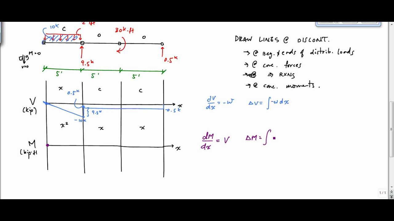
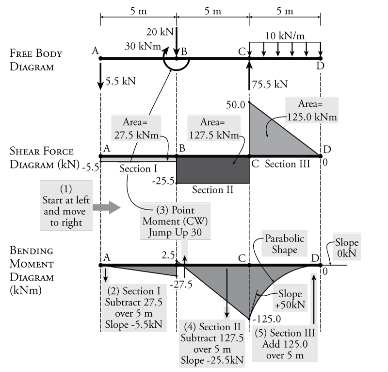
PDF Structural Axial, Shear and Bending Moments Shear and bending moment diagrams depict the variation of these quantities along the length of the member. Proceeding from one end of the member to the other, sections are passed. After each successive change in loading along the length of the member, a FBD (Free Body Diagram) is drawn to determine the equations express-ing the shear and ...

Shear force and bending moment diagrams. | Download ...
en.wikipedia.org › wiki › Introduction_to_generalIntroduction to general relativity - Wikipedia Notable examples of great interest to astronomers are quasars and other types of active galactic nuclei. Under the right conditions, falling matter accumulating around a black hole can lead to the formation of jets, in which focused beams of matter are flung away into space at speeds near that of light.
Determining the Shear Force and Bending Moment Equations of ...
Shear force and bending moment diagram and examples ... Calculate the shear force and bending moment for the beam subjected to a concentrated load, then draw the shear force diagram (SFD) and bending moment diagram (BMD). Answer: By taking the moment at A, MA = 0 - RBy × 5 + 15 × 3 = 0 RBy = 9 kN Fy = 0 RAy + RBy = 15 RAy = 15 - 9 RAy = 6 kN Fx = 0 , RAx = 0 Shear force and bending moment diagram
4.3 Determinate Beam Analysis | Learn About Structures

Bending Moment and Fixed Moment Calculations | Civil ...

Shear Force and Bending Moment Diagrams - Wikiversity
Shear Force and Bending Moment diagram for Simple supported beam
Shear and moment diagram
Shear force and Bending Moment diagram for overhanging beam

Moment Diagrams Constructed by the Method of Superposition ...

Shear force and bending moment diagram and examples - PIGSO ...
How to Draw Moment Diagrams | ReviewCivilPE
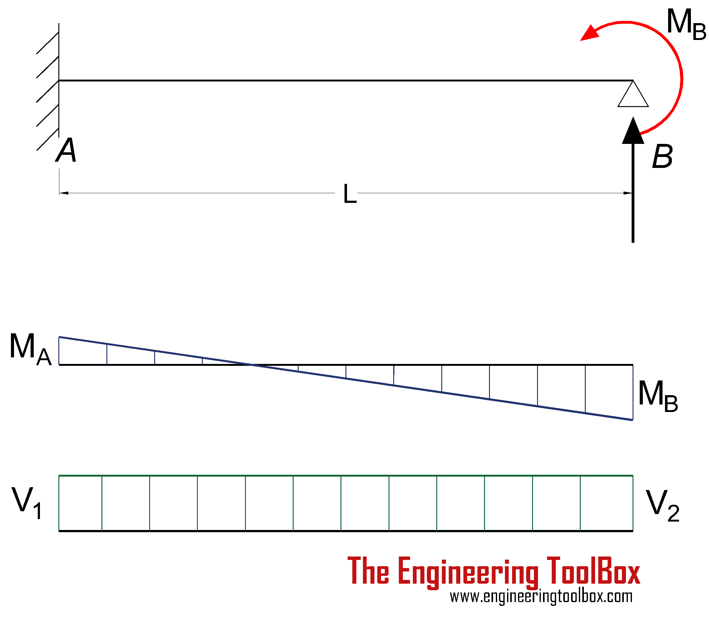
Beams - Fixed at One End and Supported at the Other ...
Chapter 4: Internal Forces in Beams and Frames” in ...

Drawing Shear Force, Bending Moment Diagram » File Exchange ...

structural engineering - How to plot bending moment diagram ...
Module -4 Shear Force and Bending Moment Diagrams
Recitation #5 Understanding Shear Force and Bending Moment ...

Brief Information About Shear Force And Bending Moment ...
6.2 Shear/Moment Diagrams – Engineering Mechanics: Statics

Draw Shear Force And Bending Moment Diagram For Cantilever ...
The Ultimate Guide to Shear and Moment Diagrams ...
civil engineering beams columns | shear force & bending ...

Bending Moments

Draw the shear force and bending moment diagrams of the beam ...

Bending Moment Diagram - an overview | ScienceDirect Topics

Shear force and bending moment diagram practice problem #2
Determining the Shear Force and Bending Moment Equations of ...
0 Response to "41 bending moment diagram examples"
Post a Comment