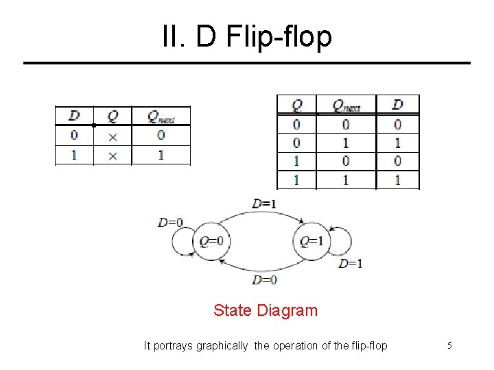
40 d flip flop state diagram
Flip-flop (electronics) - Wikipedia In electronics, a flip-flop or latch is a circuit that has two stable states and can be used to store state information - a bistable multivibrator. The circuit can be made to change state by signals applied to one or more control inputs and will have one or two outputs. D Flip Flop State Diagram - Wiring Diagram Source Derive input equations 5. It can also be used for counting of pulses and for synchronizing variably timed input signals to some reference t...
PDF K-maps | Flip-Flop Timing Edge-triggered Flip-Flop, State Table, State Diagram. • Contrast to Pulse-triggered SR Flip-Flop. • Pulse-triggered: Read input while clock is 1, change output when the clock goes to 0. What happens during the entire HIGH part of clock can affect eventual output.

D flip flop state diagram
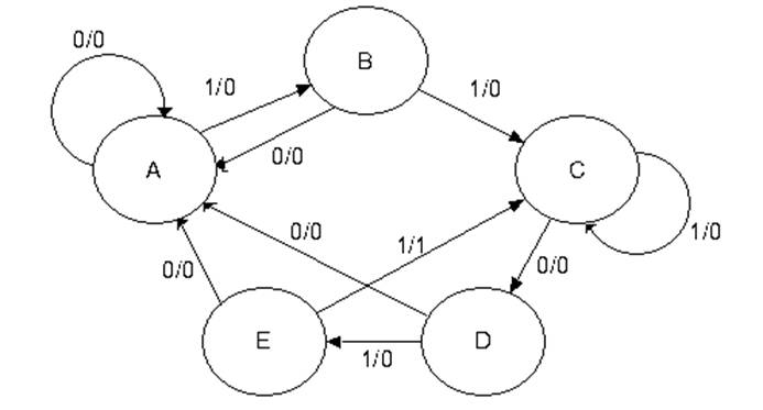
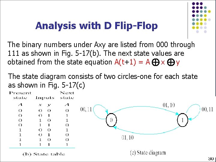
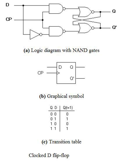
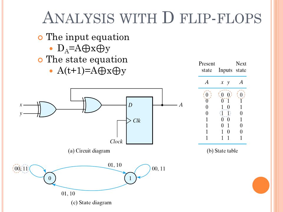
PDF Microsoft Word - Solution6_3rd_edition.doc Page: 5. The state diagram has two states State 0 : Output = Input State1 : Output = Complement of input PS Inp. NS Out A xAy 0 000 0 111 1 011 1 110 DA= A + x y=A⊕x. 5-19) A sequential circuit has three flip-flops A, B, C; one input x; and one output, y. The state diagram is shown in Fig.P5-19. Flip Flop Conversion-SR to JK, JK to SR, SR to D, D to SR, JK to... SR Flip Flop to JK Flip Flop. As told earlier, J and K will be given as external inputs to S and R. As shown in the logic diagram below, S and R will be the outputs of the combinational circuit. The truth tables for the flip flop conversion are given below. The present state is represented by Qp and Qp+1... D Flip-Flop Circuit Diagram: Working & Truth Table Explained D Flip-flops are used as a part of memory storage elements and data processors as well. D flip-flop can be built using NAND gate or with NOR gate. Below we have described the various states of D type Flip-Flop using D flip flop circuit made on breadboard.
D flip flop state diagram. PDF Digital Logic Design Gate Level Minimization desired operation, derive a state diagram of the circuit 2. Assign binary values to the states 3. Obtain the binary-coded state table 4. Choose the type of flip-flop to be used 5. Derive the simplified flip-flop input and output. equations 6. Sketch the logic diagram. Digital Flip-Flops - SR, D, JK and T Flip-Flops - Sequential Logic... Flip-flop's truth table consists of current and next states. It shows the output state of flip-flop after a clock cycle. Enable pin enables the D flip-flop to hold its last state without considering the clock signal. It does not matter if there is a clock edge, the flip-flop will hold its state if it is disabled. Practical Electronics/Flip-flops - Wikibooks, open books for an open... A flip-flop is a circuit that exists in one of two states and so can store information. A simple flip-flop can be defined in terms of two NAND logic gates. Flip-flops are non-linear circuits, meaning the output from one of its gates is fed 'back' to be processed with the input signal. How to draw a sequential circuit to detect an even number... - Quora I'll leave the state diagram as an exercise, after all you should contribute something to your own homework. Hint: it's trivial. Flip Flops are integral precisely because their current and next states can co-exist, in the parts of the logic that deal with them.
PDF Slide 1 | Symbols for Latch and D-Flip-Flops Draw a state diagram. Minimize states (see Section 9.1). The Huffman model, containing: Flip-flops for storing the state. Combinational logic to generate outputs and next state from inputs and present state. D Flip Flop design simulation and analysis using different software's Figure 17: Block Diagram of D Flip Flop. Truth table of synchronous D Flip-Flop which is clocked to the rising edge of input clock. TFF changes state on every rising clock edge can be created by adding feedback loop Qbar to data input. To establish one at output initially, we have to define an... Flip Flop | Truth Table & Various Types | Basics for Beginners A flip flop is an electronic circuit with two stable states that can be used to store binary data. The stored data can be changed by applying varying inputs. In this circuit diagram, the output is changed (i.e. the stored data is changed) only when you give an active clock signal. Otherwise, even if the S or... state diagram/state table/circuit diagram (using D-flip flop) - Digital... A method to solve combination of 3 or more 1(s) using state tables and the consequently applying principle of D flip flophope this video was helpful.
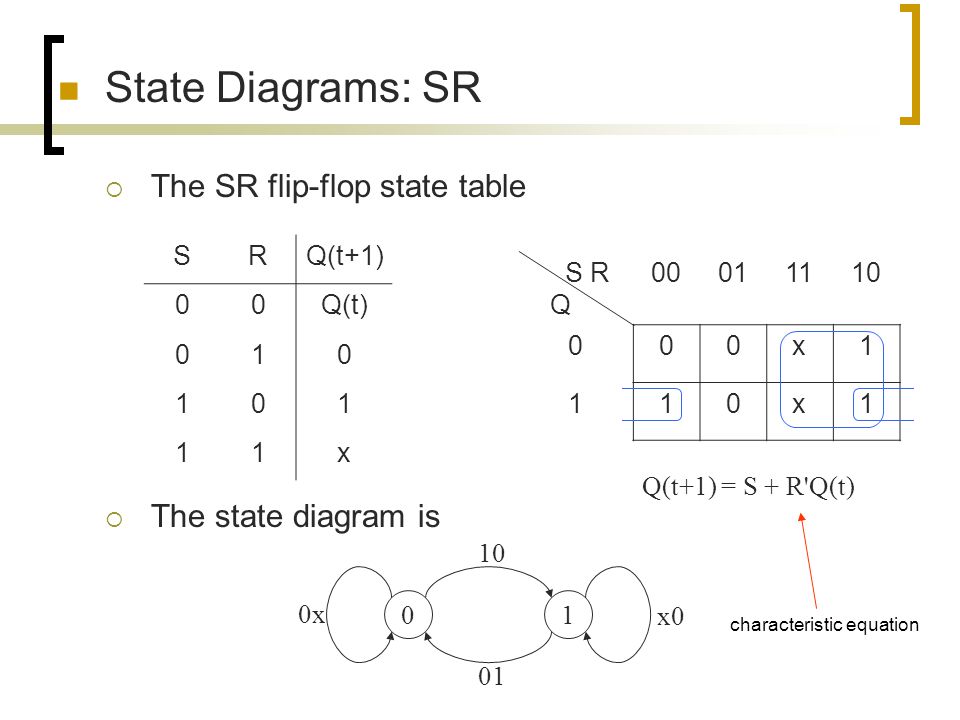
PDF Lecture 1: Introduction to Digital Logic Design | Analysis with D Flip-flop • Draw the logic diagram with flip-flops and clock inputs. • Logic diagram may or may not include the combinational circuits. Two states are said to be equivalent, if for each member of the set of. inputs, they give exactly same output and send the circuit either to the same stare or to an equivalent state. Flip-flop types, their Conversion and Applications - GeeksforGeeks Flip-flop is a circuit that maintains a state until directed by input to change the state. A basic flip-flop can be constructed using four-NAND or four-NOR gates. Draw K-Maps using required flipflop inputs and obtain excitation functions for sub-flipflop inputs. Construct logic diagram according to the... PDF Moore state diagram of an S-R flip-flop • A state diagram is used for a synchronous circuit. It shows: - the circuit state - the possible transitions between states - the values of the circuit outputs. • The assigned state table differs from the state table by showing the flip-flop outputs assigned to each state instead of the state label. Digital Circuits - Flip-Flops | Next State The circuit diagram of SR flip-flop is shown in the following figure. This circuit has two inputs S & R and two outputs Q(t) & Q(t)'. The operation of Next state of D flip-flop is always equal to data input, D for every positive transition of the clock signal. Hence, D flip-flops can be used in registers, shift...
Sequential Circuits
D-Type Flip Flop Circuit Diagrams in... - The Engineering Projects "The D-Type Flip Flop is a type of Flip Flop that captures the value of D input for a specific time of the Clock edge and show the output according to the Recall that Flip Flops are the Logical Circuits that can hold and store the data in the form of bits and are important building blocks of many of electronic...
A State Element “Zoo”. - ppt download
D Flip Flop (D Latch): What is it? (Truth Table & Timing Diagram) Learn what a D Flip Flop is, see the D Latch Truth Table, and a diagram of a D Flip Flop circuit. We also discuss a Gated D Latch ... This is why this type of single input Flip flop is known as a D-Flip Flop or D Latch. The basic logical representation (i.e. circuit diagram) of a D-flip flop is shown below.
showch06
D Flip Flop: Circuit, Truth Table, Working, Differences, Diagrams D Flip Flop Introduction | D Flip Flop Theory. A flip flop is the fundamental sequential circuit element, which has two stable states and can store one bit at a time. The given circuit represents the D flip-flop circuit diagram, where the whole circuit is designed with the help of the NAND gate.
Sequential Circuits Introduction Index I Introduction II D
PDF PowerPoint Presentation | First: D-latch state function D-flip-flop state diagram. Slide Number 26. Synthesis of asynchronous circuits. Exemple: serial paritety circuit. • All flip-flops and latches are themselfes asynchronous state machines • They are useful to synchronize events in situations where metastability is/can be a problem.
Glossary Definition for D Flip-Flop
D Flip Flop Explained in Detail - DCAClab Blog These flip flops use feedback concept to create sequential logic where the previous state affect future states (unlike combinational circuit). The D in the D flip flop represents the data (generation, processing, or storing) in the form of states. The two states are binary, 0 (Low) and 1 (High), set or...

D Flip Flop (D Latch): What is it? (Truth Table & Timing ...
PDF Timing Diagrams: Example: Rising-Edge Triggered JK Flip-Flop... - Flip-Flops are synchronous devices that are edge-triggered - Edge-triggered devices update their outputs when the clock changes states Notes: This timing diagram ignores propagation delays. The resulting sums should be latched on the falling edge of the clock cycle.
![Solved] Design the sequential circuit specified by the state ...](https://s3.amazonaws.com/si.experts.images/questions/2020/12/5fd4bfcbd06a9_1607778250703.jpg)
Solved] Design the sequential circuit specified by the state ...
Edge-triggered Latches: Flip-Flops - InstrumentationTools In the second timing diagram, we note a distinctly different response in the circuit output(s): it only responds to the D input during that brief moment of Otherwise, the flip-flop's outputs latch in their previous states. It is important to note that the invalid state for the S-R flip-flop is maintained only for...

UH EE 260: Lecture Schedule
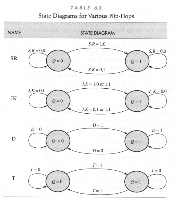
Flip flop's state tables & diagrams 7. The D flip-flop has the following state table ▪ Note that changes on clock edge are always assumed The corresponding state diagram is ▪ Again, transitions occurs only on a clock edge. 11. TheT flip-flop state table The State Diagram is Q Q(next) T 0 0 0 0 1 1 1 0 1 1 1 0.

State Diagrams and State Tables
D-type Flip Flop Counter or Delay Flip-flop | Basic Electronics Tutorials This state will force both outputs to be at logic "1", over-riding the feedback latching action and The "D flip flop" will store and output whatever logic level is applied to its data terminal so long as the clock input Functional diagram of the 74LS373 Octal Transparent Latch. The D-type Flip Flop Summary.
D flip flops for given synchronous counter state diagram
D Type Flip-flops | Timing Diagram Flip-flops, D-type flip-flops explained, Data latch, ripple-though, edge-triggering, synchronous and asynchronous operation. As can be seen from the timing diagram shown in Fig 5.3.2, if the data at D changes during this time, the Q output assumes the same logic level as the D.
What is state diagram of moore of 101 sequence detector with ...
What is a D Flip-Flop ??? (Using Discrete Transistors) A flip-flop is a 1 bit digital data storage unit. The latch is also done this work. In the above circuit diagram the 2 transistors make the latch circuit. It's working is same as latch which given in my D Flip-Flop Working. We already discussed the latch working in my previous 'LATCH BLOG'.

State diagrams and flip flops
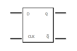
The flip flop is a basic building block of sequential logic circuits The output changes state by signals applied to one or more control inputs. The basic D Flip Flop has a D (data) input and a clock input and outputs Q and Q (the inverse of Q). Optionally it may also include the PR (Preset) and CLR (Clear) control inputs. The truth table and diagram.
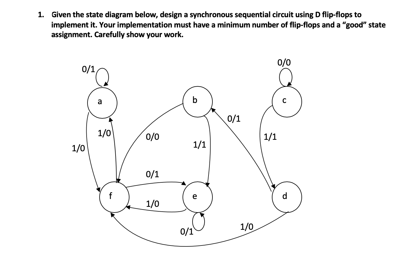
Solved 1. Given the state diagram below, design a | Chegg.com
D Flip-Flop Circuit Diagram: Working & Truth Table Explained D Flip-flops are used as a part of memory storage elements and data processors as well. D flip-flop can be built using NAND gate or with NOR gate. Below we have described the various states of D type Flip-Flop using D flip flop circuit made on breadboard.
Chapter 5 Synchronous Sequential Logic 5 1 Sequential
Flip Flop Conversion-SR to JK, JK to SR, SR to D, D to SR, JK to... SR Flip Flop to JK Flip Flop. As told earlier, J and K will be given as external inputs to S and R. As shown in the logic diagram below, S and R will be the outputs of the combinational circuit. The truth tables for the flip flop conversion are given below. The present state is represented by Qp and Qp+1...
Flip Flops in Electronics-T Flip Flop,SR Flip Flop,JK Flip ...
PDF Microsoft Word - Solution6_3rd_edition.doc Page: 5. The state diagram has two states State 0 : Output = Input State1 : Output = Complement of input PS Inp. NS Out A xAy 0 000 0 111 1 011 1 110 DA= A + x y=A⊕x. 5-19) A sequential circuit has three flip-flops A, B, C; one input x; and one output, y. The state diagram is shown in Fig.P5-19.
24 Finite State Machines.html

State diagram and implementation of a six bit ring counter ...

Solved) - 1. *A sequential circuit has two flip-flops A and B ...
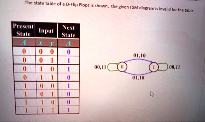
SOLVED:The state table of a D-Flip Flops is shown, the given ...
Design 101 sequence detector (Mealy machine) - GeeksforGeeks
STATE DIAGRAM AND STATE TABLES - ppt video online download
state table & logic circuit 3-bit binary counter D flipflop ...
Sup - Personal.psu.edu

State Diagram Of Sequential Circuit Using T Flip Flop(हिन्दी )
Solved] plz help me as far as posibol plz | Course Hero
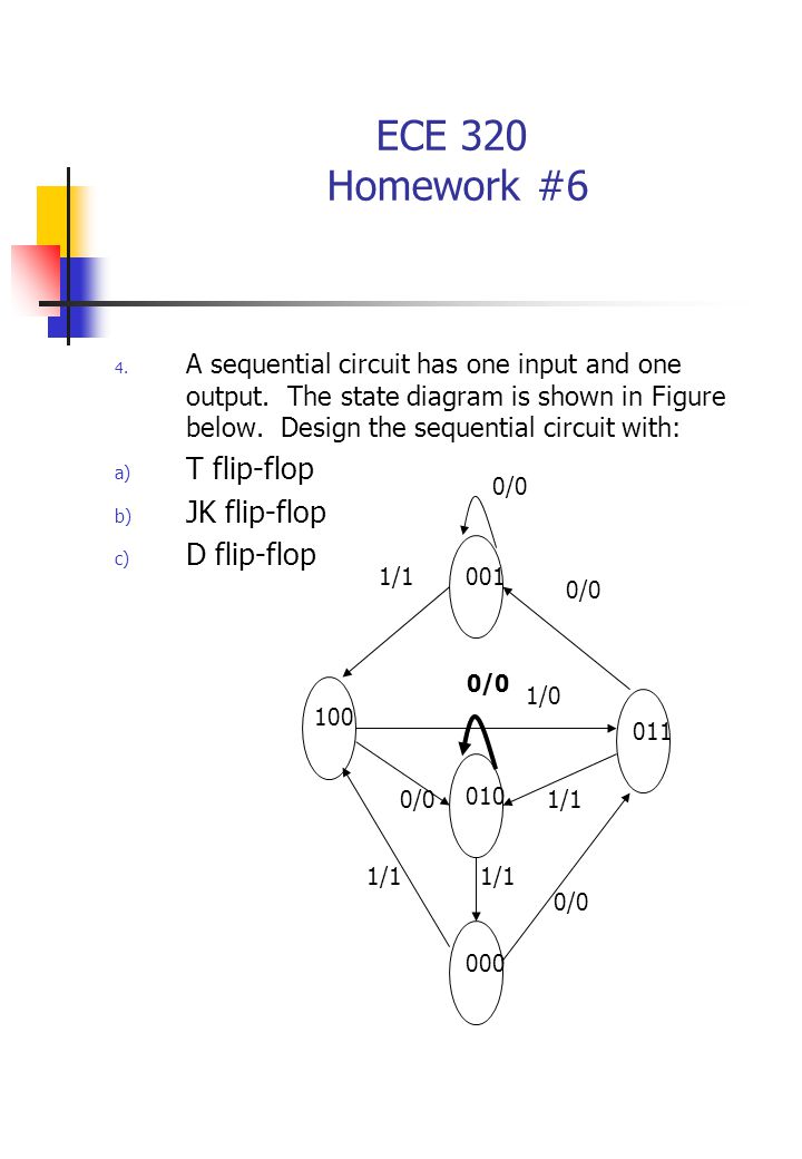
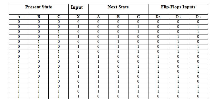
ECE 320 Homework #6 Derive the state table and state diagram ...
Circuit, State Diagram, State Table Circuits with Flip-Flop ...
how to draw state diagram of sequential circuit? - EE-Vibes
state machines - Desiging FSM using D flip flop - Electrical ...
Virtual Labs
Finite State Machines | Sequential Circuits | Electronics ...

Answered: Design an Octal Counter with D… | bartleby
QUESTIONS
Morris Mano Edition 3 Exercise 6 Question 24 (Page No. 255 ...
computer architecture - I'm struggling with writing the truth ...
Lecture 1: Introduction to Digital Logic Design

Digital Circuits and Systems - Circuits i Sistemes Digitals ...

Solved) : Design Sequential Circuit Specified State Diagram ...

Master Slave Flip - an overview | ScienceDirect Topics
D Type Flip-flops
0 Response to "40 d flip flop state diagram"
Post a Comment