39 time delay relay wiring diagram
Dayton Time Delay Relay Wiring Diagram | Diagram, Relay ... The Macromatic SFP120A100 is a pump seal failure relay. This 8 Pin plug-in relay has an input voltage of 120V. This single channel relay is made to monitor for leaks in submersible pump seals and has an output of 10A SPDT. The sensitivity is adjustable and can be preset to meet the resistance level needed. The single channel feature means that ... GI-2.0: Typical Wiring Diagrams - Rockwell Automation the diagram. In following the electrical sequence of any circuit, however, the wiring diagram does not show the connections in a manner that can be easily followed. For this reason a rearrangement of the circuit elements to form a line diagram is desirable. The line diagram (sometimes referred to as an
off delay timer relay wiring diagram - IOT Wiring Diagram Off Delay Timer Relay Wiring Diagram. By IOT | December 11, 2021. 0 Comment. Solid state timer relay electrical academia using time delay relays to cycle a traffic signal 555 ic motor control systems part c electromechanical worksheet digital circuits how wire an off dol starter overrun the for 5 minutes quora circuit before turn on working ...
Time delay relay wiring diagram
ICS Time Delay Module Applications and Wiring Application Wiring for "Fixed" DC Time Delay Module Figure 3. KH1 Series fixed time ON DELAY external connection diagram. View is from the flat side with the catalog numbers. Time delay is factory preset to one specific time, 5 seconds for example. Module LOAD at Pin 2 is a relay coil. Time Delay Relay Basics: Relay Circuit and Applications 2020-10-20 · On Delay Relay Contacts Wiring . Ⅴ Time Relay Applications. In Flash Control. Two-time relays cooperate with each other to provide constant frequency on/off pulses of the contacts, sending intermittent power to the light. In Furnace Safety Purge Control. Before the combustion furnace can be safely ignited, the fan must run for a certain period of time to clean … Timer And Contactor Wiring Diagram Pdf - Wiring Diagram On delay timer circuit diagram wiring diagram contactor with push button circuit diagram of delay timer on off power off delay timer circuit diagram 2 way lighting circuit triggering transformer push button fan switch light activated switch circuit diagram wd081 text. Each component should be placed and linked to other parts in particular manner.
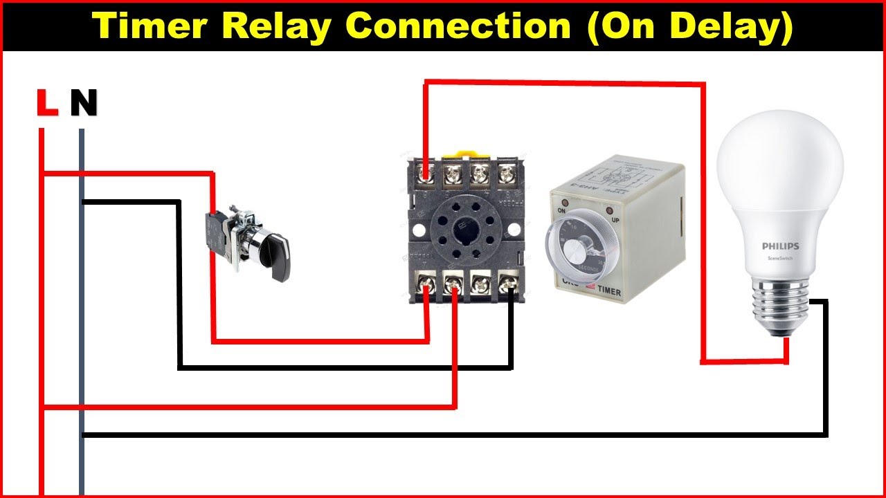
Time delay relay wiring diagram. on delay timer wiring diagram | 8 pin timer relay wiring ... on delay timer wiring diagram | 8 pin timer relay wiring diagram Assalam-o-AlaikumHiFriendsI am Muhammad Bilal Welcome to our youtube channel Mian Electric .... Air Handler Fan Relay Wiring Diagram - Wiring Diagram Rly02807 American Standard Trane Air Handler Fan Time Delay Relay - Air Handler Fan Relay Wiring Diagram. Wiring Diagram includes the two illustrations and step-by-step instructions that might allow you to definitely actually construct your undertaking. This is beneficial for both the folks and for specialists that are seeking to find out ... Installation Instructions TMR5 Series Non-programmable ... Non-programmable Plug-In Time Delay Relays Wiring Wire the socket per the wiring diagram on the side of the time delay relay. Note: For products that use a Control Switch to initiate the unit, this Control Switch is a dry-type contact (applying voltage to the pins could damage the unit). For products using a Power Trigger to initiate the PDF DROK Timer Relay P3: Relay will turn ON for time OP after getting a trigger signal and then turn relay OFF.Module will reset and stop timing if it gets a trigger signal again during delay time OP. P4: Relay will turn OFF for time CL after getting a trigger sighal and then relay will turn ON for time OP.Relay will turn OFF after finish timing.
8 Pin Relay Wiring Diagram - Wiring Diagram 2020-12-31 · 8 pin relay wiring diagram – You will want a comprehensive, professional, and easy to know Wiring Diagram. With such an illustrative guide, you’ll be capable of troubleshoot, stop, and complete your tasks easily. Not merely will it help you attain your desired results quicker, but also make the complete procedure less difficult for everybody. PDF Multi-functional Timer relay. Upon application of input voltage, the time delay relay is ready to accept a trigger. When the trigger is applied, the time delay (t1) begins. At the end of the time delay (t1), the output is energized. When the trigger is removed, the output remains energized for the time delay (t2). PDF Installation Instructions THR-3816U, THR-3836U & THR-3856U ... Encapsulated Time Delay Relays December 2020, Rev D 901-0000-295 DANGER! ... Trigger to initiate the unit as indicated by the dotted line in the wiring diagrams above. For Triggered DC Input Voltages, make sure the polarity matches the connection diagram. Guardmaster Configurable Safety Relay Wiring Diagram The CR30 safety relay performs the logic that monitors the interlock and the drive, and allows access to the hazard under safe conditions. For partial body access, the 440G-LZ can be substituted for the TLS-ZR.
Time Delay Relays - littelfuse.com Time Delay Relays DELAY-O-MAKE TDM / TDMH / TDML Series Delay-on-Make Timer L1 N/L2 Wiring Diagram Relay contacts are isolated. Ordering Information MODEL INPUT VOLTAGE DELAY RANGE TDM120AL 120 V ac 1–1023 s in 1 s increments TDM12DL 12 V dc 1–1023 s in 1 s increments TDM230AL 230 V ac 1–1023 s in 1 s increments off delay timer relay wiring diagram - Wiring Diagram and ... Apr 20, 2021 · Solid state timer relay electrical academia using time delay relays to cycle a traffic signal 555 ic motor control systems part c electromechanical worksheet digital circuits how wire an off dol starter overrun the for 5 minutes quora circuit before turn on working principle electrical4u timers advanced logic flip flops shift registers counters ... Dayton Time Delay Relay Wiring Diagram Download - Wiring ... dayton time delay relay wiring diagram - What's Wiring Diagram? A wiring diagram is a schematic which uses abstract pictorial symbols to exhibit each of the interconnections of components in a very system. Time Delay Relay Basics: Relay Circuit and Applications Introduction. Time relay refers to a kind of relay whose output circuit needs to make an obvious change (or contact action) after adding (or removing) the input action signal in a specified and accurate time. It is an electrical component used in a circuit with a lower voltage or a smaller current to switch on or off a circuit with a higher voltage and larger current.
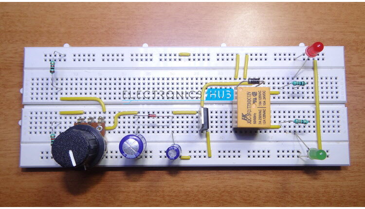
How To Build Time Delay Relay Circuit
Off Delay Timer Relay Wiring Diagram - U Wiring Off Delay Timer Relay Wiring Diagram. Amarante Pruvost. August 20, 2021. Find Instant Quality Info Now. Get Results from multiple Engines. This Post Is About The Staircase Timer Wiring Diagram In The Diagram I Use The On Delay Timer Finder 8 Pin Relay Re Electrical Circuit Diagram Timer Diagram.
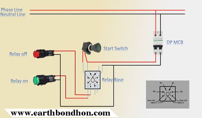
Timer Testing Wiring Diagram – Earth Bondhon
8 Pin Relay Wiring Diagram - Wiring Diagram 8 Pin Relay Wire Diagram Wiring Schematic | Wiring Diagram - 8 Pin Relay Wiring Diagram. You'll be able to usually depend on Wiring Diagram as an essential reference that can help you save time and cash. With all the help of this e-book, you'll be able to easily do your own wiring tasks.

AH3 delay timer wiring with push button | Timer, Electrical ...
Electrical Symbols | Switches and Relays - ConceptDraw A relay is a switch that is operated by electricity. Switches are made to handle a wide range of voltages and currents; very large switches may be used to isolate high-voltage circuits in electrical substations. Pic. 1. Switches and Relays Library. ConceptDraw DIAGRAM is a powerful software for creating professional looking electrical diagram quick and easy. For this purpose you can …
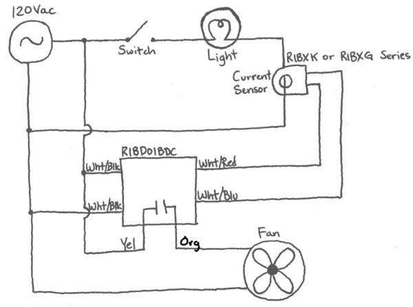
A Delayed Bathroom Exhaust Fan - Functional Devices, Inc.
PDF Multi-functional Timer relay. the time delay (t1) begins. At the end of the time delay (t1), the output is energized. When the trigger is removed, the output remains energized for the time delay (t2). At the end of the time delay (t2), the output is de-energized and the time delay relay is ready to accept another trigger. If the trigger is removed during time delay
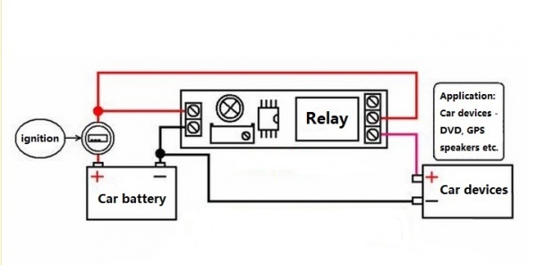
Timer Adjustable 12V Delay Realy Module - ITEAD Wiki
Trane Fan Relay Wiring Diagram - Wire Collection of air handler fan relay wiring diagram. Replacing time delay relay and checking operation. It reveals the elements of the circuit as streamlined shapes as well as the power and signal links in between the tools. Rly02807 relay as they were on the rly02257 relay. Downflow furnace models fd14dclfr000d fd17dclfr000d fd21dclfr000d ...
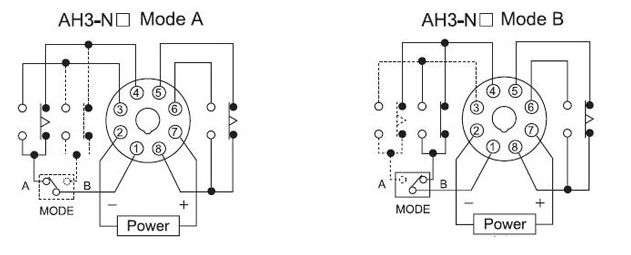
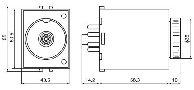
AH3-N 3A On-delay time super time delay relay 220v_Inductive ...
PDF Time Delay Relays - Application Data Time delay relays are simply control relays with a time delay built in. Their purpose is to control an event based on time. ... They are represented by the dotted lines in the wiring diagrams. Note that the user must provide the voltage to power the load being switched by the output contacts of the time delay relay.

Time Delay Relay Basics: Relay Circuit and Applications
How to Wire A Time Delay Relay Diagrams - autocardesign Mar 23, 2019 · How to Wire A Time Delay Relay Diagrams– wiring diagram is a simplified enjoyable pictorial representation of an electrical circuit.It shows the components of the circuit as simplified shapes, and the gift and signal contacts along with the devices.
ST3PF time delay relay electronic general purpose relay ...
Wiring Diagram For Time Delay Relay - Wiring Diagram Line Time delay relay circuit with 555 using timer ic electromechanical relays worksheet digital circuits to cycle a traffic signal tdr 120vac 24vdc 326 327 series on ...

Time-Delay Electromechanical Relays Worksheet - Digital Circuits
Zone selective interlocking - Eaton restraining its tripping and continuing to do its time delay . Similarly if the fault current is over the Main breaker’s Short Time protection level the Main breaker will be restrained by continuing to do its time delay and send a zone output signal to the protective relay EDR-5000 in zone 1 .
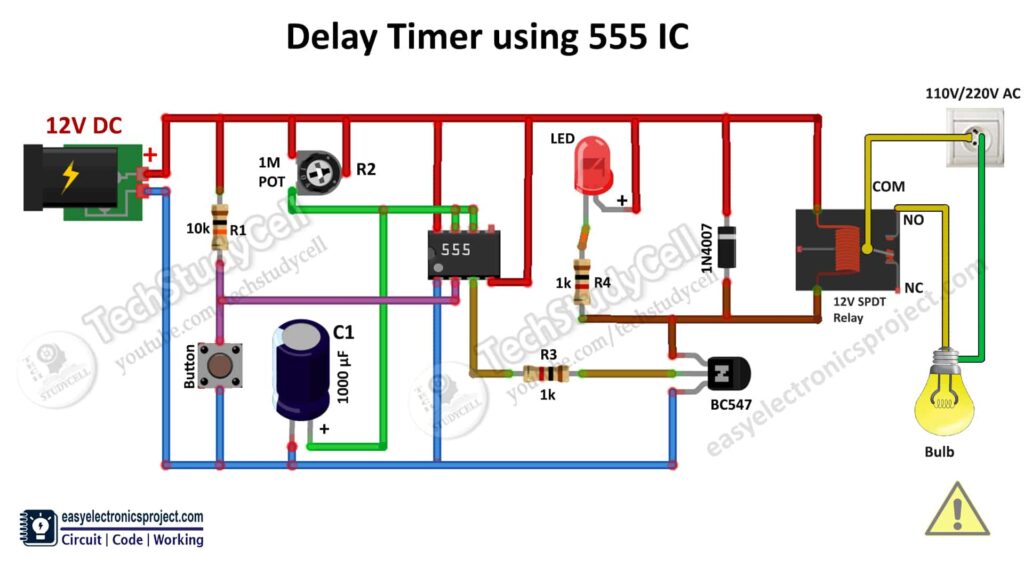
Time Delay Relay circuit using 555 timer IC - Electronics ...
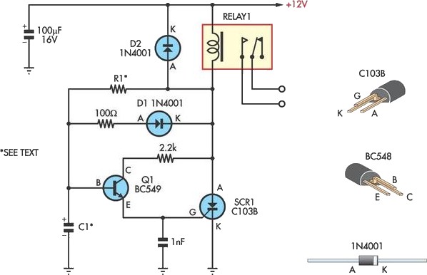
12V Time Delay Relay Circuit - ElectroSchematics.com Time Delay Relay Circuit Schematic. Power to the circuit can be derived from a standard 12 volt transformer with rectifier and smoothing capacitor. Use a socket to connect the TV as shown. SMD, one of our top members has given us an alternative version of the circuit that seems to be working quite well. SMD's 12 volt time delay relay ...
Time Delay Relay TDR 120VAC 24VDC
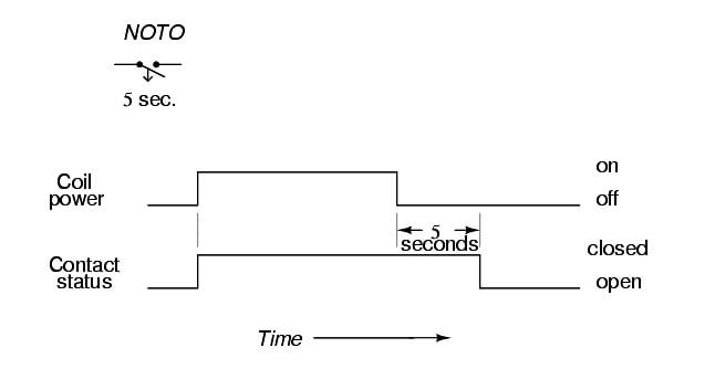
Time-delay Relays | Electromechanical Relays | Electronics ... Time delay relays are built in these four basic modes of contact operation: 1: Normally-open, timed-closed. Abbreviated "NOTC", these relays open immediately upon coil de-energization and close only if the coil is continuously energized for the time duration period. Also called normally-open, on-delay relays. 2: Normally-open, timed-open.

TGM | Delay on Break Relay Timer
HYUNDAI Fault Codes DTC - Car PDF Manual, Wiring Diagram ... Looking for a 2011 wiring diagram for the windows have stopped working battery went dead trying to locate the window relay if anybody knows please help me thank you Sports and imports Columbus, GA 706-681-2388

Using Time Delay Relays to Cycle a Traffic Signal
8 Pin Relay Wiring Diagram - Wirings Diagram 8 Pin Relay Wiring Diagram - 8 pin ac relay wiring diagram, 8 pin flasher relay wiring diagram, 8 pin octal relay wiring diagram, Every electrical structure is made up of various different components. Each component should be set and linked to other parts in specific way. Otherwise, the arrangement will not function as it should be.

How On Delay Timer Works | Star Delta Timer Diagram
Electrical Control Panel Wiring Diagram Pdf - U Wiring 2021-10-31 · Control and Relay Panel Wiring Diagram Pdf wiring diagram is a simplified adequate pictorial representation of an electrical circuit. Needed for this equipment. Basics 19 Instrument Loop Diagram. A wiring diagram usually gives guidance very nearly the relative incline and union of. Electrical control panel wiring diagram pdf. Wiring Diagram Images …

Time Delay Relay Basics: Relay Circuit and Applications
Pcbfm131 Time Delay Relay Wiring Diagram This pcbfm131 time delay relay wiring diagram, as one of the most full of life sellers here will extremely be along with the best options to review. Residential Duct Systems - Manual D-Acca 2017-02 The Third Edition of ANSI/ACCA Manual D is the Air Conditioning Contractorsof America procedure for sizing

How to wire Pin timers
On Delay Timer Connection Diagram and Testing - ETechnoG The common terminal or 15 of the timer is connected with the A1 terminal so it also gets the 230V power supply. Now, let's start the test to understand how it is working. Step 1. The main power supply is off condition, so all lamps also off condition. Now we set the time delay 40 sec. Step 2.

Simple Way to Make a Time Delay Relay?
Beuler Relay Wiring Diagram - schematron.org Install thermostat into the head or intake manifold. Route the black wire from the relay to the thermostat and cut it to length. Crimp one of the red female spade.Relay Wiring Diagram. A relay is typically used to control a component that draws high amperage.

Time Delay Relay Circuit with 555
Arduino - LED - Blink Without Delay | Arduino Tutorial In the previous tutorial, we learned to blink LED by using the delay method. That method blocks Arduino from doing other tasks. In this tutorial, we are going to learn another method to blink LED without blocking other tasks. The detail instruction, code, wiring diagram, video tutorial, line-by-line code explanation are provided to help you quickly get started with Arduino.

Time delay switch wiring diagram diagram base website wiring ...
Time Delay Relay Wiring Diagram Download - Wiring Diagram Sample Jul 16, 2018 · Name: time delay relay wiring diagram – enter image description here; File Type: JPG; Source: electronics.stackexchange.com; Size: 60.67 KB; Dimension: 377 x 342; What is really a Wiring Diagram? A wiring diagram is an easy visual representation with the physical connections and physical layout of the electrical system or circuit.

Time Delay Relay using 555 Timer, Proteus Simulation and PCB ...
Understanding Time Delay Relay Functions | Macromatic Time delay relays are simply control relays with a time delay built in. Their purpose is to control an event based on time. The difference between relays and time delay relays is when the output contacts open & close: on a control relay, it happens when voltage is applied and removed from the coil; on time delay relays, the contacts can open or ...
ICS Time Delay Module Applications and Wiring
AutoCAD Electrical Tutorials Webinars Tips and Tricks Electrical Computer-Aided Design Consulting for AutoCAD, AutoCAD Electrical 2017, Toolbox/WD, VIA/WD, and Promis-e. Industrial controls design specialists, including schematic, wiring diagram, bill-of-materials, wire from/to list, and panel layout, since 1988. Experienced with DIN, IEC, AS, and U.S. standards. AutoCAD Electrical training courses and training material, …
8 Pin Timer Relay Wiring Diagram | Basic Timer Connection And Function |
Timer And Contactor Wiring Diagram Pdf - Wiring Diagram On delay timer circuit diagram wiring diagram contactor with push button circuit diagram of delay timer on off power off delay timer circuit diagram 2 way lighting circuit triggering transformer push button fan switch light activated switch circuit diagram wd081 text. Each component should be placed and linked to other parts in particular manner.
Time-delay Relays - InstrumentationTools
Time Delay Relay Basics: Relay Circuit and Applications 2020-10-20 · On Delay Relay Contacts Wiring . Ⅴ Time Relay Applications. In Flash Control. Two-time relays cooperate with each other to provide constant frequency on/off pulses of the contacts, sending intermittent power to the light. In Furnace Safety Purge Control. Before the combustion furnace can be safely ignited, the fan must run for a certain period of time to clean …
Handy Time Delay With Relay Output Circuit Diagram
ICS Time Delay Module Applications and Wiring Application Wiring for "Fixed" DC Time Delay Module Figure 3. KH1 Series fixed time ON DELAY external connection diagram. View is from the flat side with the catalog numbers. Time delay is factory preset to one specific time, 5 seconds for example. Module LOAD at Pin 2 is a relay coil.

I am trying to wire a Dayton 1EGC6 - 11 pin time delay relay ...
timer - How to wire this delay relay switch - Electrical ...

On Delay Timer Connection Diagram and Testing - ETechnoG
Adjustable Timer Circuit Diagram with Relay Output

Delay timer for motor or pump/ 120Volt to 240Volt
Price history & Review on DC 5V Real time Timing Delay Timer ...
Price history & Review on DC 5V Real time Timing Delay Timer ...

12V Relay With Timer Switch : 4 Steps - Instructables

Timer Delay Relay DC 5V 12V 24V On Off Timer Module Trigger Cycle Dual MOS Delay Control Board with Digital Tube Display and Protective Shell for ...

TGMLB | Delay on Break Relay Timer

How to wire Pin timers

How to wire an ON Delay Relay Timer | Honda Shadow Forums
DH48S Digital Time On Delay Relay DPDT 12V 24V DC 120V 380V ...

How to connect and set analog timer relay

On Delay Timer Connection with Contactor - ETechnoG
0 Response to "39 time delay relay wiring diagram"
Post a Comment