39 submersible pump installation diagram
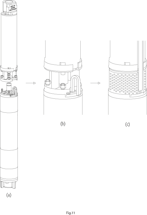
PDF Installation and Operation Manual - APEC PUMP installation, take care not to damage the insulation on the cable. Instructions for Coupling Pump End Assembly to Motor (if not assembled) The pump end is designed to be coupled to a 100mm electric submersible motor equipped with a NEMA flange and shaft protrusion. To assemble the pump and motor: 1. Pump - Wikipedia A pump is a device that moves fluids (liquids or gases), or sometimes slurries, by mechanical action, typically converted from electrical energy into hydraulic energy. Pumps can be classified into three major groups according to the method they use to move the fluid: direct lift, displacement, and gravity pumps.
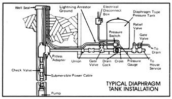
Pump Installation - Tuhorse Pumps - Submersible Well Pumps Submersible Deep Well Pump Installation - Domestic water system. For a printer friendly version, click here. Diagram of deep well submersible well pump installation with sanitary well seal and pitless adapter. Below is a video demonstration of assembling the pump and motor: YouTube. Tuhorse North America. 6 subscribers.
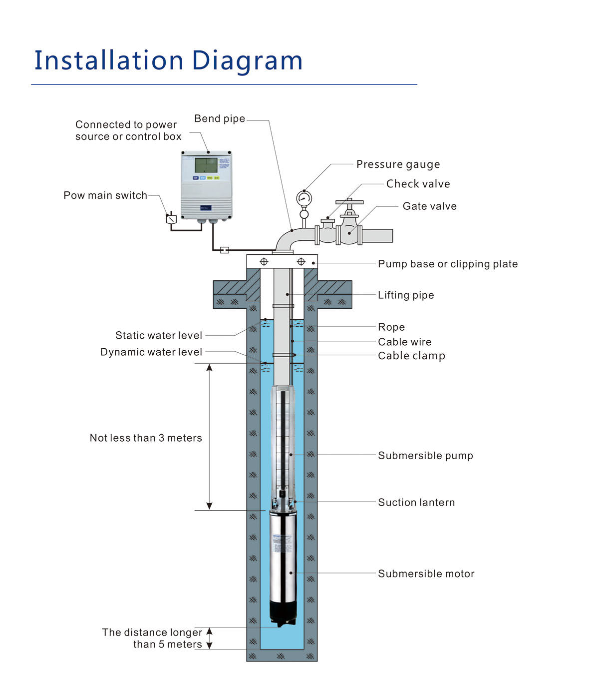
Submersible pump installation diagram
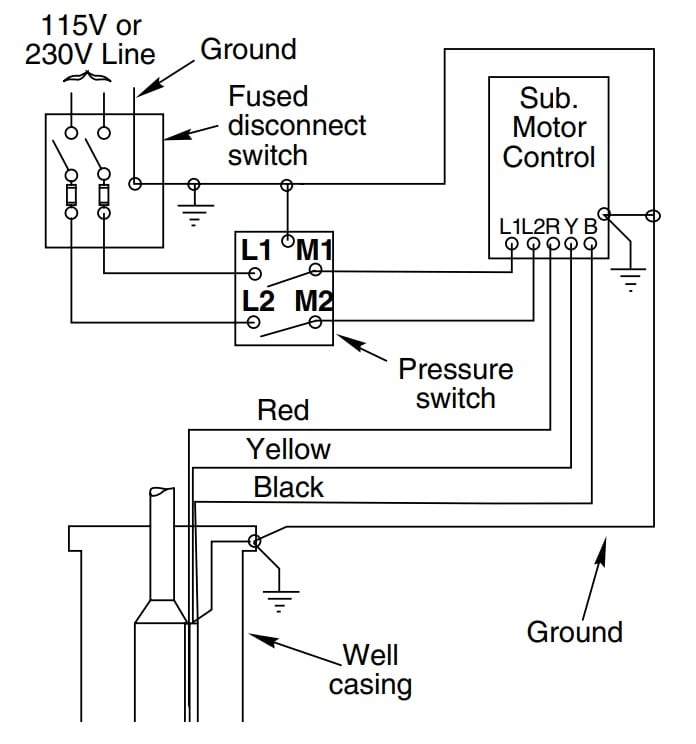
Permanent Magnet Motor - an overview | ScienceDirect Topics The UHS submersible pump is a modular multistage centrifugal pump designed for a speed range of 1,000–12,000 RPM. The floater design pump is equipped with stages distributed in several pump modules, with seven to nine stages per module depending on pump model. Wiring Diagram for 220-volt Submersible Pump The wiring diagram of the 2-wire 220-volt submersible pump is given below to make your job even more accessible. In the upper portion of this diagram, you will find a section named "Pressure Switch.". There will be two more sub-sections in this section: "Motor" and "Panel.". You will have to do it in this way because the conduit ... A Complete Guide of All Submersible Pump Components For proper installation in a submersible pump application, you must strip 1/4" of insulation from the wire. The heat shrink tube is then slid over one end, the wires insert into the stakon connector. The heat shrink is then crimped to attach the stakon to the wire. Before you shrink the tube, ensure the tube is centred over the stakon connector.
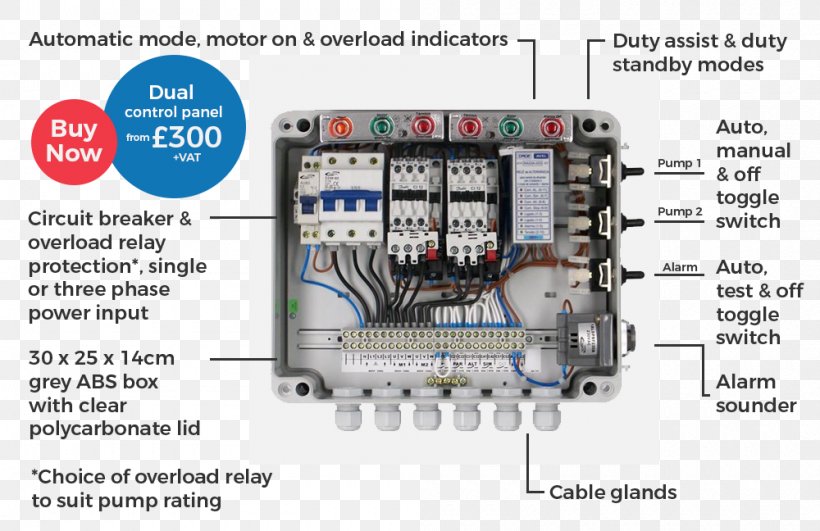
Submersible pump installation diagram. Wiring a Submersible Pump - The Steps to Follow ... If you have any doubt about the connecting process of the 3-wire submersible pump wiring diagram, just follow the steps below: Step-1: Gather All Necessary Equipment and Material. Through the whole process, the single-phase 3-wire submersible pump wiring diagram will help you a lot to stick in the right path. Complete Guide to Thermostat Wiring Heat Pump | Step by Step ... Nov 16, 2021 · Heat pump thermostat wiring chart. When it comes to the Honeywell thermostat wiring heat pump, you are wiring the heat pump thermostat over to the indoor wire handler you going to typically run 18:8 thermostat wires. You can run 18:10 thermostat wire which gives you additional wires for a potential outdoor sensor. Submersible Well Pump Wiring Diagram - Wirings Diagram As stated earlier, the lines at a Submersible Well Pump Wiring Diagram signifies wires. At times, the cables will cross. But, it doesn't imply link between the wires. Injunction of 2 wires is generally indicated by black dot in the intersection of two lines. There'll be main lines which are represented by L1, L2, L3, and so on. ScubaTANK - Dutypoint The range comprises the single pump WX1 and twin pump WX2 models, available in duty/assist and duty/standby configurations, with a variety of pumps to select. Capacities range from 175 to 2,250 litres.
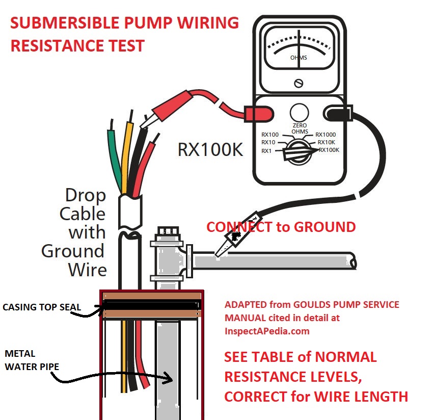
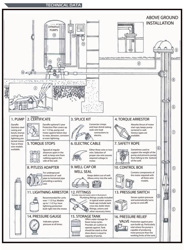
PDF Well Pump & Pressure Tank Diagram - Clean Water Store PUMP 3 1. Check Valve Located at the top of the pump to prevent back flow into pump and hold the head of water in the system. 2. Torque Arrestor Installed directly above Submersible Pump to protect pump and well components from starting torque damage. 3. Safety Rope A safety line from the top of the well to the pump. 4. Pitless Adapter Two Line Jet Pumps for Water Wells: Installation & Repair ... A nice example table of Deep Well 2-Line Jet Pump Capacities for 1/2 hp and 1 hp deep well pumps is provided in the Water Ace Jet Pump Installation Manual and excerpted below to illustrate the factors that determine well pump capacity. Water Pump Setup Diagram - U Wiring Wiring Diagram For 220 Volt Submersible Pump Water Pumps Submersible Pump Submersible . Deep Well Pump Installation Instructions In 2021 Deep Well Pump Well Pump Shallow Well Jet Pump . In diagram, pump, setup, water. Leave a Reply Cancel reply. Your email address will not be published. Required fields are marked * Comment * How to Install and Wire a Well Pump - Well Pump ... Understanding Well Pump Wiring Diagrams. Learning how to read well pump wiring diagrams is necessary to install a well pump properly. Deep submersible well pumps will be either 2-wire or 3-wire well pumps, and 3-wire well pumps will need a separately installed control box. Two-Wire Well Pump Wiring Diagrams
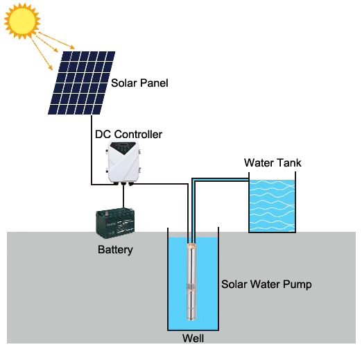
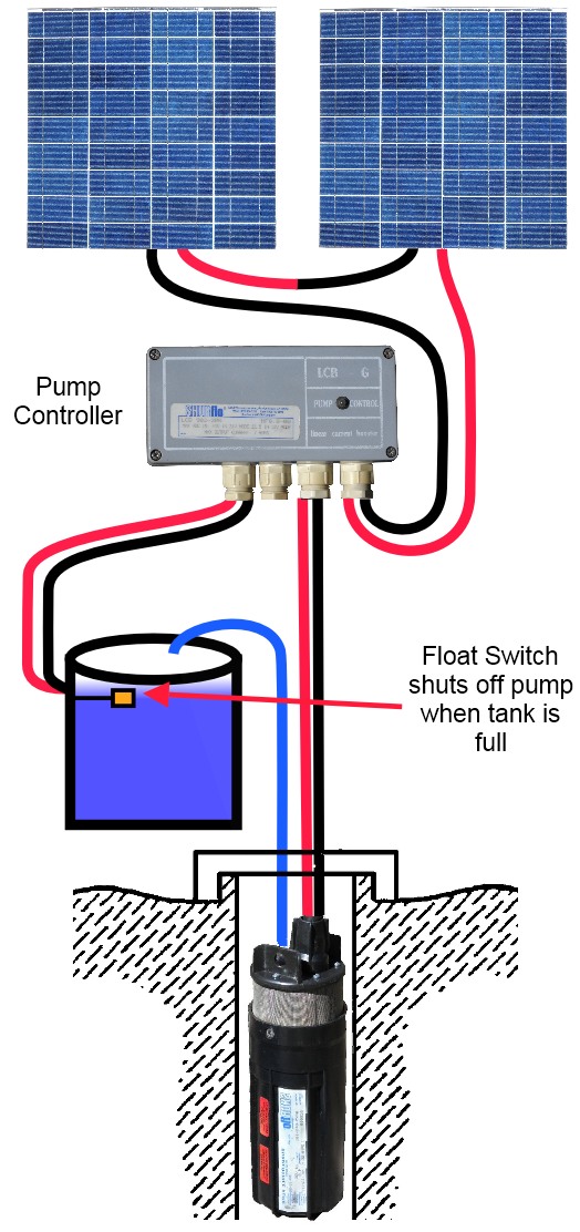
Components of a Typical Submersible Pump Installation Typical pumps used in a submersible pump installation are either a two or three wire pump. The two wire pumps have the starting capacitor built into the submersible motor whereas the three wire pumps do not have the capacitor built into the motor, they require a control box which is normally found in the pump house at the well head. 2 Wire and 3 Wire Submersible Well Pump Motor Wiring ... In this video, I go over the differences of a 2 wire and a 3 wire submersible well pump.This is associated with the starting components for the pump and whet... Submersible Water Pump Circuit Diagram - Wiring Diagram ... Water pump wiring troubleshooting repair diagrams how to install and wire a well installation guide run submersible using relays what relay configuration can be quora electrician single phase starter facebook aim manual page 54 motors controls motor maintenance north america franklin electric schematic diagram of pv pumping system scientific circuit control panel station pumps electronics ... (PDF) SOLAR POWERED WATER PUMPING SYSTEM - Academia.edu The manufacturer claims 55% more energy is collected with the tracker. The submersible motor was a DC electric motor rated for 24 V and had a peak current draw of 3.1 A and was mounted directly to the pump. The pump was a diaphragm type pump constructed of marine bronze and stainless steel.
3 Phase Submersible Pump Wiring Diagram - Diagram Sketch 3 Phase Submersible Pump Wiring Diagram. angelo on January 22, 2022. Automatic Water Level Controller Wiring Diagram For 3 Phase Motor Submersible Pump Submersible Pump Water Pump Motor Electrical Installation. 3 Phase Submersible Pump Wiring Diagram With Dol Stater Electrical Online 4u Electrical Circuit Diagram Electrical Diagram Motor.
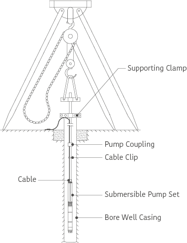
INSTALL A SUBMERSIBLE PUMP: 6 Lessons for doing it right Install a Submersible Pump Lesson#4: Follow These Tricks for Lowering a Submersible Pump Using a grinder to remove the sharp burr on the top edge of a steel well casing. Getting pipe and pump and wires into the well in one piece is heavy work, and there are a couple of things you can do to make success more certain.
Submersible Well Pump Accessories Installation Diagram Submersible Well Pump Accessories Installation Diagram. This illustration is for educational purposes ; It is not intended as an installation guide.
Submersible Well Pump Wiring Diagram - easywiring Submersible well pump wiring diagram. Here is the complete guide step by step. Assortment of submersible pump control box wiring diagram. It shows the elements of the circuit as simplified forms and also the power as well as signal links between the devices. Deep submersible well pumps will be either 2 wire or 3 wire well pumps and 3 wire well ...
Submersible Pump Wiring Diagram - Diagram Sketch A Guide Of Auxiliary Contact S And It 39 S Uses And Working In Contactor X2f Motor St Submersible Pump Electrical Circuit Diagram Electrical Wiring Diagram. 44 Luxury Single Phase Submersible Pump Starter Wiring Diagram Submersible Well Pump Jet Pump Well Pump. 18 Franklin Electric Wiring Diagram Submersible Well Pump Jet Pump Well Pump.
Submersible Pump Wiring Diagram - U Wiring Grundfos sq submersible pump 3 76mm well borehole sq 1-35 ms3 058kw 1x230v 5060hz. However it does not mean link between the cables. Submersible well pump wiring diagrams. Everbilt 12 hp submersible 2-wire motor 10 gpm deep well potable water pump. 3-wire deep well submersible pump.
Submersible Pump Control Box Wiring Diagram - YouTube Welcome to @Electric Wiring SchoolToday we learn Submersible Pump Control Box Wiring Diagram.A submersible pump pushes water to the surface by converting rot...
PDF TYPICAL SUBMERSIBLE PUMP INSTALLATION - Grover Electric TYPICAL SUBMERSIBLE PUMP INSTALLATION 1. We recommend the captive-air style pressure tank. It has significantly higher drawdown than a standard pressure tank and eliminates water logging problems. The air level in the tank should be 2 lbs. less than pressure switch turn-on level. For a 30-50 switch, this would be 28 lbs. of air with the tank ...
A Complete Guide of All Submersible Pump Components For proper installation in a submersible pump application, you must strip 1/4" of insulation from the wire. The heat shrink tube is then slid over one end, the wires insert into the stakon connector. The heat shrink is then crimped to attach the stakon to the wire. Before you shrink the tube, ensure the tube is centred over the stakon connector.
Wiring Diagram for 220-volt Submersible Pump The wiring diagram of the 2-wire 220-volt submersible pump is given below to make your job even more accessible. In the upper portion of this diagram, you will find a section named "Pressure Switch.". There will be two more sub-sections in this section: "Motor" and "Panel.". You will have to do it in this way because the conduit ...
Permanent Magnet Motor - an overview | ScienceDirect Topics The UHS submersible pump is a modular multistage centrifugal pump designed for a speed range of 1,000–12,000 RPM. The floater design pump is equipped with stages distributed in several pump modules, with seven to nine stages per module depending on pump model.


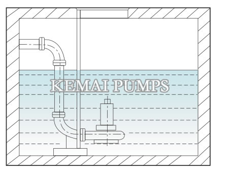





![Installation types of sewage dewatering pumps [5].(a) Wet-pit ...](https://www.researchgate.net/profile/Constantinos-Psomopoulos/publication/324692619/figure/fig1/AS:618474053320705@1524467113393/Installation-types-of-sewage-dewatering-pumps-5a-Wet-pit-installation-b-Portable.png)






0 Response to "39 submersible pump installation diagram"
Post a Comment