41 function generator circuit diagram
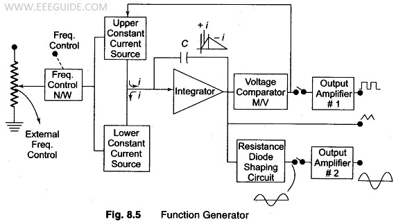
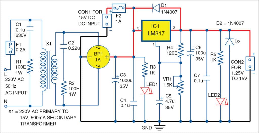
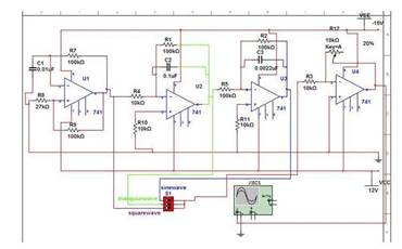
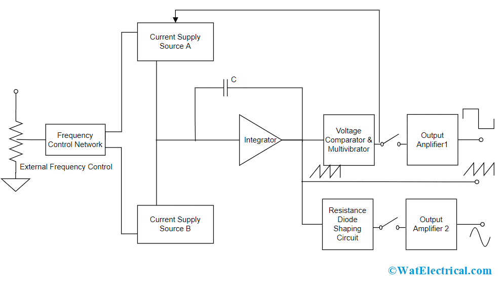
The figure below shows the block diagram of the function generator- A frequency control network used here whose frequency is controlled by the variation in the magnitude of current. The current sources 1 and 2 drives the integrator. By using Function Generator, we can have a wide variety of waveforms whose frequency changes from 0.01 Hz to 100 KHz. Function Generator Circuit Diagram Notes . The circuit needs a dual power supply. A +15 -15 power supply as shown in the circuit is enough for the purpose. The frequency of the output wave form can be adjusted using R7.It must be a 100K Log POT. The duty cycle can be adjusted using R3 , a 1K POT.
A simple function generator circuit with diagram and schematics using ICL8038, which is a pulse generator IC which generates waveforms of sine,square,sawtooth,triangular and pulse. Bill Porter. Electronic Oddities. Electronics Basics. Electronic Schematics. Signal Processing. Circuit Diagram. Arduino. Waves.
Function generator circuit diagram
Nov 10, 2018 · Sweep your Function Generator Schematic Circuit Diagram. Admin November 10, 2018. 0 187 1 minute read. Function generators built around the XR2206 have always had an excellent price/performance ratio, and the IC although ‘obsolescent’ is still available. If your generator does not have built-in sweep (‘wobbulator’) capability, a small ... Fiddler's Thinkings. In principle, the XR-2206 chip itself is a monolithic function generator integrated circuit capable of producing high quality sine, square, triangle, ramp, and pulse waveforms of high-stability and accuracy. The output waveforms can be both amplitude and frequency modulated by an external voltage. Function Generator - Simple Circuit Diagram Tag: Function Generator Triangle Waveform Signal Generator September 25, 2011 Rust A symmetrical, 10 mV peak to peak triangle waveform can be generated by the circuit depicted in the following schematic diagram. This circuit is featured with alternative DC biased output which can be used to feed an ADC.
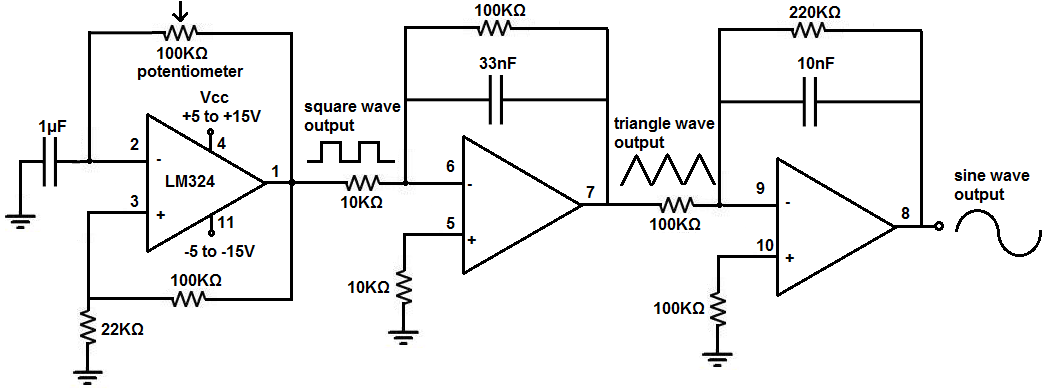
Function generator circuit diagram. The XR-2206 is a monolithic function generator integrated circuit capable of producing high quality sine, square, triangle, ramp, and pulse waveforms of high-stability and accuracy. The output waveforms can be both amplitude and frequency modulated by an external voltage. Frequency of operation can be selected We have used a 18-0-18 volt 2amp power transformer follow circuit diagram for more info. Frequency Generator Section- To generate a stable frequency We have used ICL8038 waveform generator is a monolithic integrated circuit capable of producing high accuracy sine, square, triangular waveform. ICL8038 and XR-2206 can help you build a Function Generator or Wavform Generator. It is needed along with the Oscilloscope and Power Supply on the Workbench. The ICL8038 waveform generator is a monolithic integrated circuit capable of producing high accuracy sine, square, triangular, sawtooth and pulse waveforms with a minimum of external ... The function generator circuit we will build with an LM324 op amp chip is shown below. The breadboard circuit of the above circuit is shown below. So above is the function generator chip we will build. So the first concern is power to the circuit. As explained above, the LM324 is powered by DC voltage through pins 4 and 11.
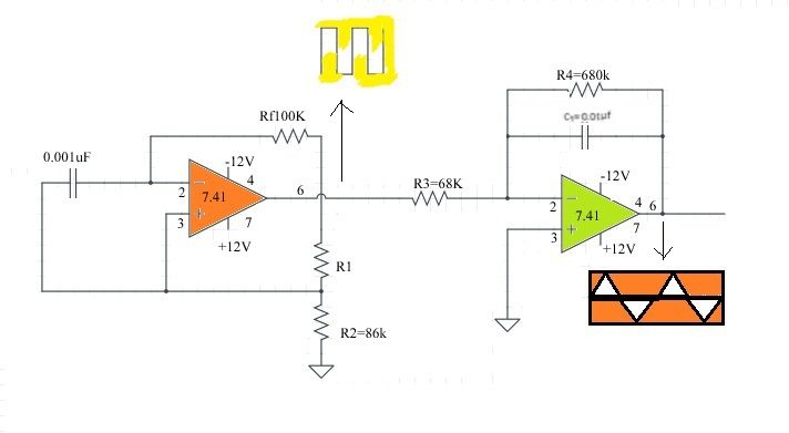
2. Function generator using op-amp LM1458. That circuit is based on a LM1458 or RC4558 capable of producing sine, square, triangular, sawtooth and pulse waveforms of high accuracy and stability…. 3. Simple Function generator by LM566. The simple Function generator two waveform, It produces triangle and square waves from 1Hz up to 1MHz. First, a function generator (also called a tone generator) is an electronic device that can output a specific waveform at a set frequency. For example, one could generate a sinusoidal signal at 60Hz. You can use it to test the inner workings of audio amplifiers, find the characteristic of op-amps and diodes, make funky noises—the list of ... The heart of the FG-500 Function Generator is the XR-2206 monolithic function generator integrated circuit. The XR-2206 is comprised of four main functional blocks as shown in the functional block diagram (Figure 1). The wave generator refers to an instrument that generates electrical test signals with the required parameters. The circuit form can be composed of op-amps and discrete components, or a single-chip integrated function generator. It is widely used in production practice and technology.
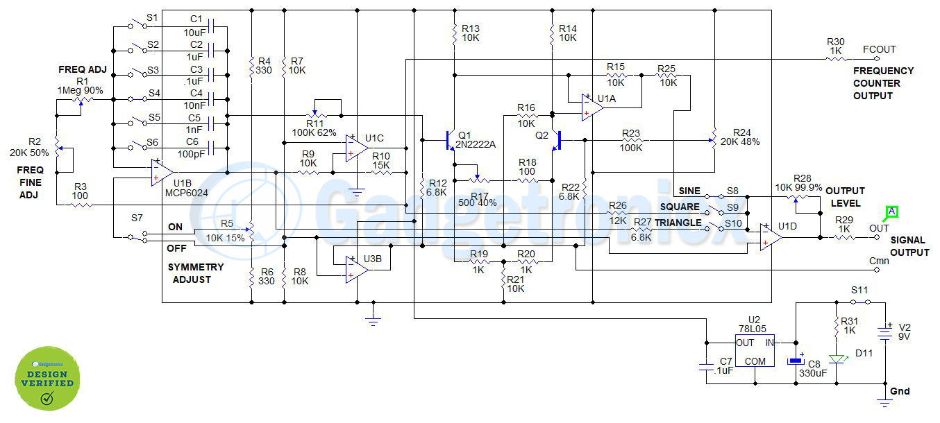
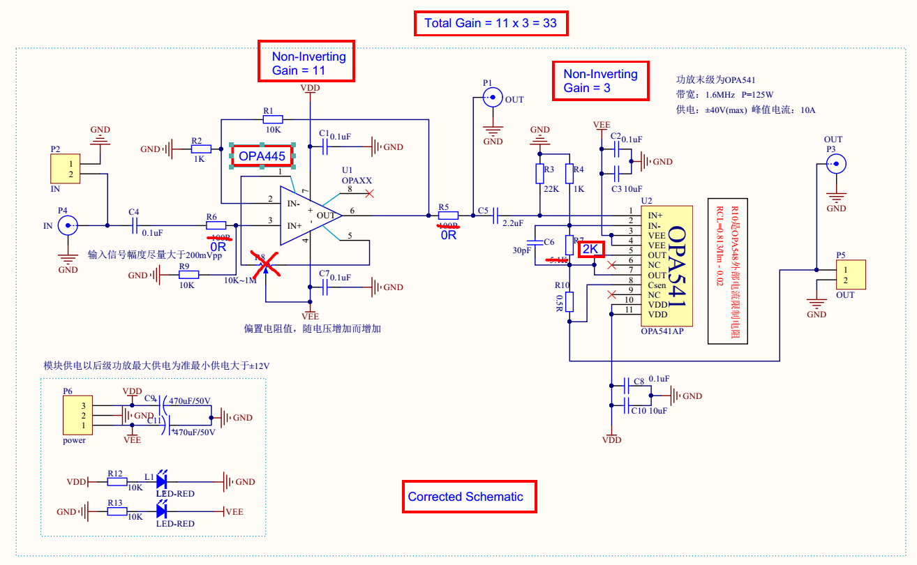
Basic diagram ICL8038 circuit Function generator Figure 1 The basic circuit of function generator using ICL8038 The Basic characteristics of the circuit with a few components, it consists of the VR1- potentiometer, the R1-resistors and the C1-capacitors to determined frequency output. Jan 06, 2021 · The complete circuit diagram for the AD9833 and Arduino Based Function Generator is shown below. We are going to use the AD9833 with Arduino to generate our desired frequency. And in this section, we will explain all the details with the help of the schematic; let me give you a brief overview of what is happening with the circuit. WORKING OF FUNCTION GENERATOR CIRCUIT: The heart of the function generator is the integrator, formed by U1A( IC MCP6024), R1, R2, S1- 6, C1 - 6, and the comparator with hysteresis, formed by U1B, R7, R8, R9, and R10. They work together in the following way. Sep 14, 2021 · The complete circuit diagram this Arduino Function Generator is shown below. The block diagram of a function generator is given in the figure. Working of Function generator circuit. The 1458 is a dual. This is a simple function generator circuit that can produce the following waveforms. Build the Function Generator 1.
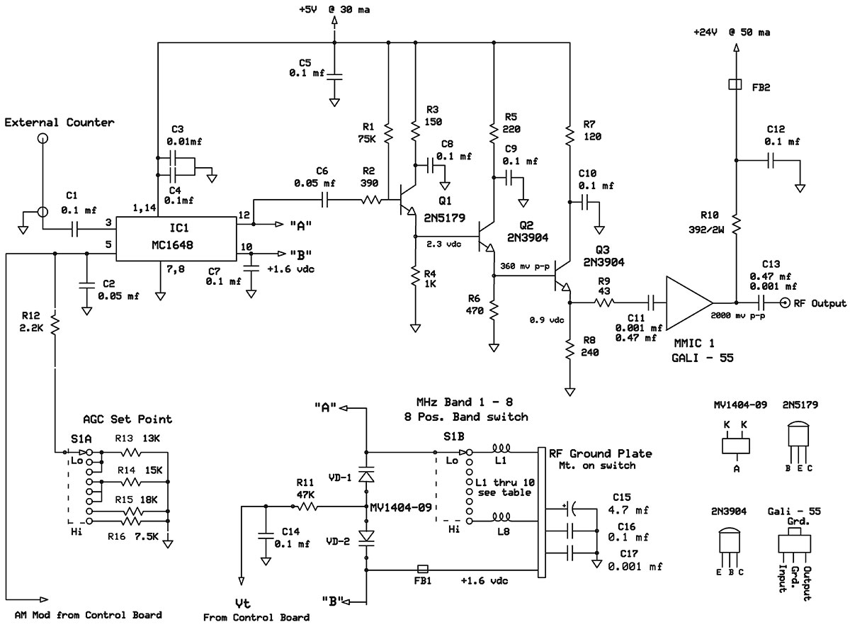
A 150 MHz RF Signal Generator for Your Test Bench | Nuts ...
Aug 13, 2017 · The block diagram of a function generator is given in the figure. In this instrument, the frequency is controlled by varying the magnitude of the current that drives the integrator. This instrument provides different types of waveforms (such as sinusoidal, triangular and square waves) as its output signal with a frequency range of 0.01 Hz to ...
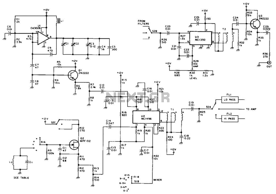
Rf Signal Generator Circuit under RF Oscillator Circuits ...
A simple function generator circuit with diagram and schematics using ICL8038, which is a pulse generator IC which generates waveforms of sine,square,sawtooth,triangular and pulse.

Simple Function Generator Circuit | Circuit diagram ...
A plug-in circuit board (\breadboard") that can be used to wire up test circuits. BNC cables. You will need a few of these. There are a variety of lengths available on racks attached to the back side of the mobile whiteboard. Let's get started by looking at some function generator signals. 1. Turn on a function generator.

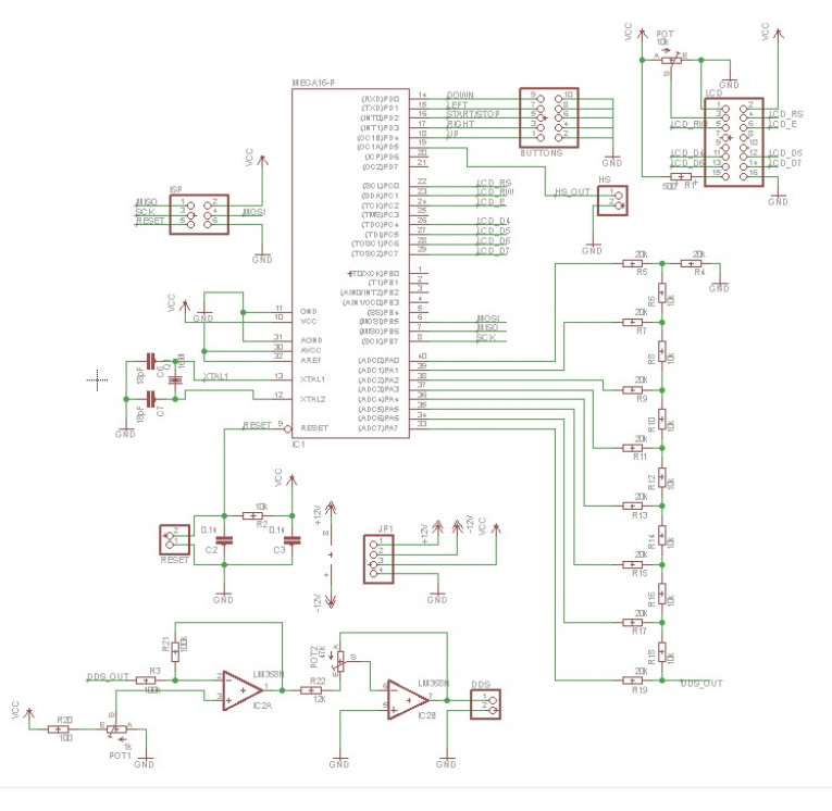
AVR DDS signal generator V2.0. Part 1. Schematic
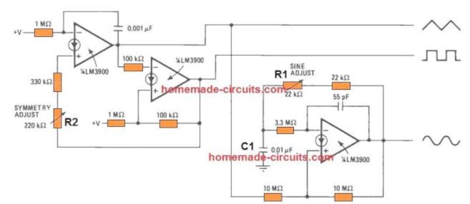
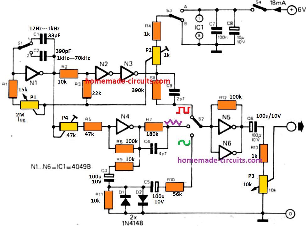
Using only one low-cost CMOS IC 4049and a handful of separate modules, it is easy to create a robust function generator that will provide a range of three waveforms around and beyond the audio spectrum. The purpose of the article was to create a basic, cost-effective, open source frequency generator that is easy to construct and used by all hobbyists and lab professionals. This goal has undoubtedly been accomplished, as the circuit provides a variety of sine, square and triangle waveforms and a frequency spectrum from roughly 12 Hz to 70 KHz employs just single CMOS hex inverter IC and a few separate elements. No doubt, the architecture may not deliver the efficiency of more advanced circuits, especially in terms of waveform consistency at increased frequencies, but it is nevertheless an incredibly handy instrument for audio analysis. For a Bluetooth Version you Can Read this Article
10 Useful Function Generator Circuits Explained - Homemade ...
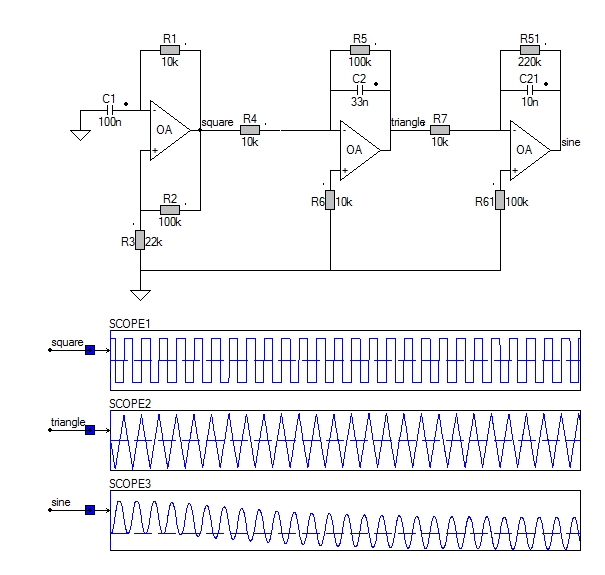
Part Four: Function Generator 1. Cascade the three previous op-amp circuits to simulate the circuit shown in Figure 5. Print out the schematic for this circuit. Figure 5: Function Generator 2. Using a transient analysis with the same parameters as in Part 1, plot the output of each op-amp (on the same plot).

Function generator circuit
Simple Function Generator Circuit Diagram. This arrangement enables the output signal at A1 and the duty cycle of the rectangular wave signal at A2 to be varied. Varying the amplification factor with P5 has no effect on the frequency set with P2. The slope of the signal edges, the transient responses, and the output voltage range (rail-to-rail ...
Mini function generator circuit using ICL8038 - EasyEDA
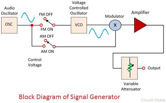
This section explains the block diagram of the function generator along with its working. Below is the block diagram picture: Block Diagram For a function generator construction, a frequency controlling network is used where is frequency is regulated by the change in the current's magnitude level.
Function Generator Block Diagram | Phase Locking in Function ...
The block diagram of function generator contains various components they are frequency control network, constant current supply source 1, constant current supply source 2, integrator, voltage comparator multivibrator, capacitor, a resistance diode shaping circuit, and two output amplifiers.
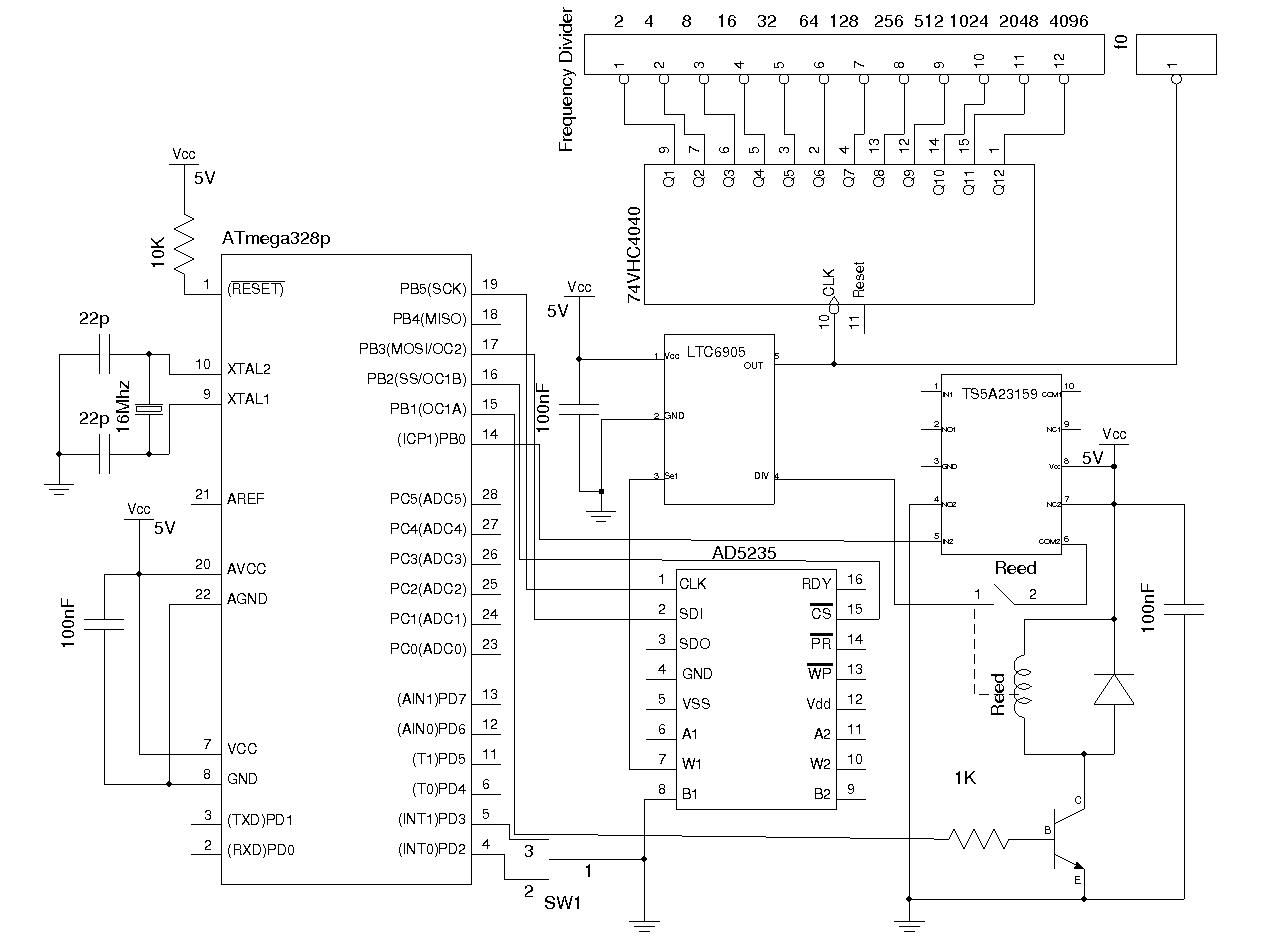
Main circuit diagram of signal generator. | Download ...
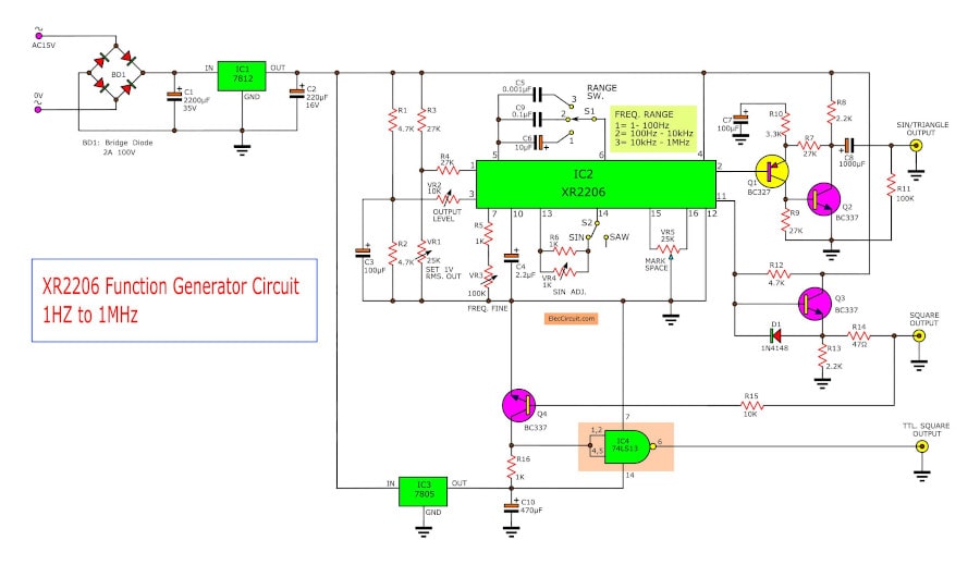
circuit board that show you where each component should be placed. The XR2206 Function Generator can generate three types of stable wave forms (sine, triangular, and square wave) with a frequency range from 1Hz to 1MHz and an adjustable amplitude. It uses an AC/DC power adapter (9-12Vdc, 30mA of current).
Function Generator Using IC 741 Op-Amp
A simple function generator circuit with diagram and schematics using ICL, which is a pulse generator IC which generates waveforms of. About the ICL Introduction. The is a function generator capable of producing sine, square, triangular, sawtooth and pulse waveforms (some at. This is the Mini function generator circuit using ICL IC-number.
XR2206 function generator circuit | ElecCircuit.com
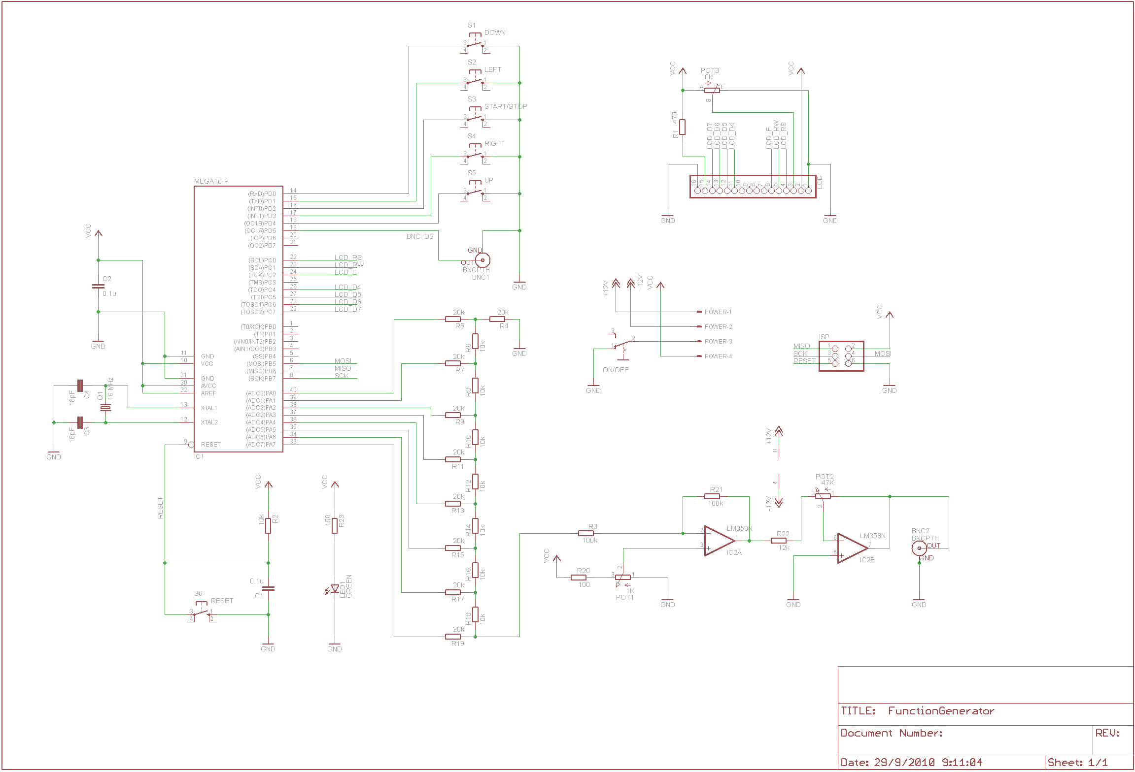
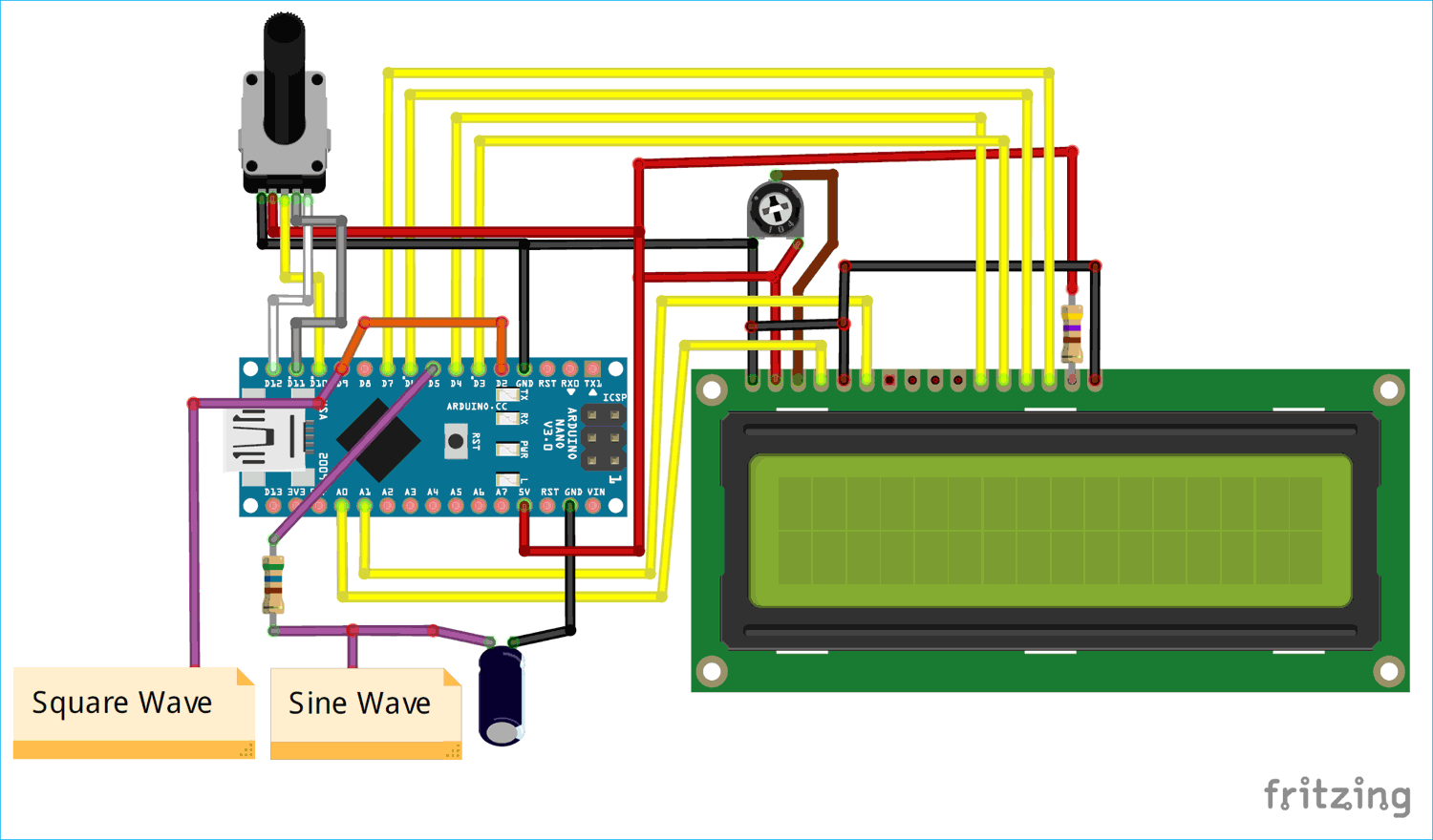
Circuit Diagram The complete circuit diagram this Arduino Function Generator is shown below. As you can see we have an Arduino Nano which acts as the brain of our project and an 16x2 LCD to display the value of frequency that is currently being generated. We also have a rotary encoder which will help us to set the frequency.
DDS Function Generator - Electronics-Lab.com
The heart of the function generator is the integrator, formed by U1B, R1, R2, R3, S1- 6, C1 - 6, and the comparator with hysteresis, formed by U1C, R6, R7, R9, and R10. They work together in the following way. U1C has its output low. When the input feeding U1Bin- is less than the reference voltage, the output of U1B ramps up.
Improved DIY Function generator project - Gadgetronicx
Function Generator - Simple Circuit Diagram Tag: Function Generator Triangle Waveform Signal Generator September 25, 2011 Rust A symmetrical, 10 mV peak to peak triangle waveform can be generated by the circuit depicted in the following schematic diagram. This circuit is featured with alternative DC biased output which can be used to feed an ADC.

Audio Frequency Generator Circuit
Fiddler's Thinkings. In principle, the XR-2206 chip itself is a monolithic function generator integrated circuit capable of producing high quality sine, square, triangle, ramp, and pulse waveforms of high-stability and accuracy. The output waveforms can be both amplitude and frequency modulated by an external voltage.
Typical RF Signal Generator.
Nov 10, 2018 · Sweep your Function Generator Schematic Circuit Diagram. Admin November 10, 2018. 0 187 1 minute read. Function generators built around the XR2206 have always had an excellent price/performance ratio, and the IC although ‘obsolescent’ is still available. If your generator does not have built-in sweep (‘wobbulator’) capability, a small ...

Electronic Projects

Arduino - XR-2206 Function Generator

Function Generator and Enclosure | Circuit Skills Video ...
Signal Generator and Inverter Using NE555 Timers | Full DIY ...
Interesting signal generators |
Caspoc Help - Signal Generator
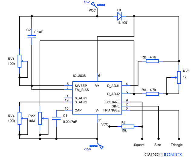
Function Generator Circuit using ICL8038 - Gadgetronicx
10 Useful Function Generator Circuits Explained - Homemade ...

XR2206 function generator working + circuit diagram - YouTube
Function Generator - Test Gears Circuits Schematics ...
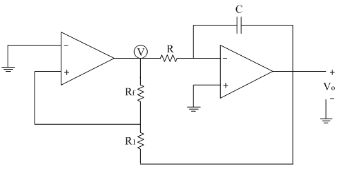
Comparator as a function generator | Analog-integrated ...
Function-Generator-Using-Op-Amps | Mini Projects ...

THE SIMPLEST FUNCTION GENERATOR BUILT ON a BREADBOARD ...

Analog Function Generator : 13 Steps (with Pictures ...
How to Build a Simple Function Generator Circuit with an ...
Function Generator : Working, Block Diagram, Types & Applications

Function Generator

Function Generator Block Diagram and Working Principle - ETechnoG
Function Generator : Circuit Diagram using LM324 IC & Its ...
Low Cost Function Generator Amplifier DIY | DMC, Inc.

Electrical Waveforms and Electrical Signals
What is a Signal Generator? - Definition & Explanation ...
4KHz-170MHz Wide Band RF Signal Generator – I – Kerry D. Wong
DIY Arduino Waveform Generator or Function Generator
Signal Generator and Inverter Using NE555 Timers | Full DIY ...
Function generator circuit composed of the ICL8038 ...
0 Response to "41 function generator circuit diagram"
Post a Comment