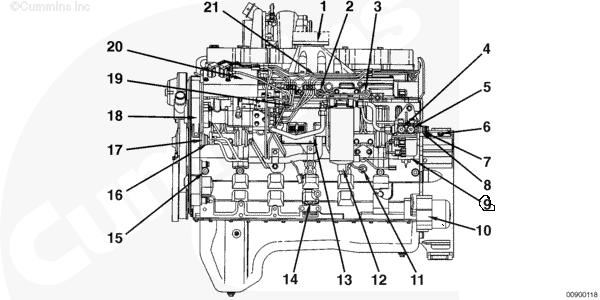
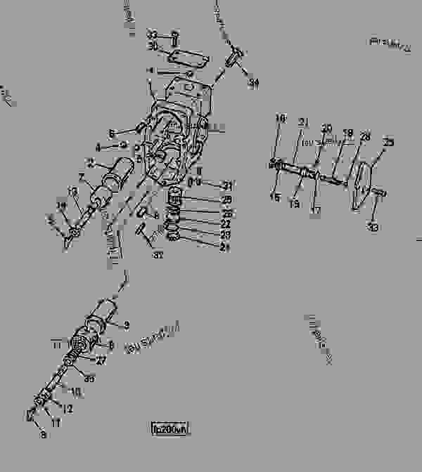
ummins fuel system diagram
About Press Copyright Contact us Creators Advertise Developers Terms Privacy Policy & Safety How YouTube works Test new features Press Copyright Contact us Creators ... Cummins N14 Manual Online: Fuel System Priming - Celect™ System. Engine Testing N14 Install the electrical wire that supplies power to the so- lenoid. NOTE: . Here you can find the latest products in different kinds of cummins n14 fuel pump diagram. We Provide 20 for you about cummins n14 fuel pump diagram- page 1.
LIKE, COMMENT AND SUBSCRIBE!!! TELL ALL YOUR FRIENDS ABOUT MY CHANNEL!If you would like to donate to the channel for better video content use the link: http...

N14 cummins fuel system diagram
Cummins Group System Exploded Diagram Section I Remove STC Engines Remove the fuel tubing and AFC air signal line: Gear pump.Cummins N14 Fuel Pump Diagrams from n14 cummins fuel system diagram. When the low-pressure turbo is spooling, the quantity of boost being fed via the intake is dramatically increased. The N14 Celect was the first Cummins ... My N14 Cummins will not start - no fuel pressure. I have replaced the fuel pump, the cam sensor and oil pressure sensor. Had this problem before. It finally started and runs fine once it starts. Now it will not start again and there is no fuel pressure. Could this be a problem with the ECM box or wiring harness? 3. Fuel grade is not correct or fuel quality is poor 4. Fuel supply line restriction between the fuel pump and the injectors 5. Air in the fuel system 6. Air intake system restriction 7. PT fuel pump AFC operation is malfunctioning or no air setting on the fuel pump is not set correctly EUGENE 4036 West 1st Ave. Eugene, OR 97402 (541) 485-1434
N14 cummins fuel system diagram. Cummins N14 Fuel System Diagram. The N14 Celect was the first Cummins engine to feature an electronic injection system. The Celect fuel system produces systematic pressure throughout each. Is the check valve in the fuel line suppose to be coming out of the I recall telling Cummins engineers at a trade show that they must have. Cummins N14 Fuel Pump Diagrams from n14 cummins fuel system diagram When the low-pressure turbo is spooling, the quantity of boost being fed via the intake is dramatically increased The N14 Celect was the first Cummins. N14 Cummins Fuel System Diagram The manual is organized to guide a service technician the logical steps of. L10, M11 & n14 Cummins Engine hard starting problem and solution if it is fuel related. Free tech support 9-9 EST 7 Days A Week. 810.653.6300 Ask For Terry How to prime the fuel system on a m11, n14, and l10 Cummins. No start after fuel filters? New fuel lines. Amazon truck, Amazon freight, Amazon trucking, owne...
Cummins PT Fuel System is a completely new application of basic hydraulic principles to the diesel engine fuel system. It is a Cummins design for Cummins Diesels. The identifying letters, "PT," are an abbreviation ... PT fuel system-Fuel flow diagram 1-1. and deliver it to individual injectors for each cylinder. 2. A means of controlling the ... Covers: Cummins N14 STC, Celect, Celect Plus Diesel Engine Pages: 1,082 Format: PDF files (zipped) File size: 80mb Works with: Windows/Mac computers Notes: Bookmarked, searchable, printable, instant download. The Cummins N14 troubleshooting & repair manual contains two volumes and is intended to aid diagnosing mechanical engine related problems and to provide recommended repair procedures per ... We carry a great selection of fuel system components, including fuel injectors, lift pumps, and fuel filters for N14 Cummins diesel engines. If you need assistance locating the part you are looking for, please use our quote request form or call us at 855.470.3525: our friendly sales representatives will answer your request promptly. 98 Cummins N14 select plus for the past 6 months fuel pressure gauge keeped on rising and no matter how many filters I changed didn't fix the problem so this...
Also, you can see many efficient recommendations, safety rules, service tools information, technical maintenance, illustrations, different diagrams, and schemes for Cummins CELECT Electronic Control System L10, M11, and N14 Engines models. Please, read and understand the basic precautions listed in the safety section before using this device. Application: Cummins N14 straight check valve fuel cooling plate outlet fitting. Cummins N14 Fuel Pump Diagrams from n14 cummins fuel system diagram When the low-pressure turbo is spooling, the quantity of boost being fed via the intake is dramatically increased The N14 Celect was the first Cummins. 7 Drawing 4954063. installations on n14 plus cummins engines. application notes the cbrake by jacobs™ model 455b and 455c engine brakes are for use on cummins n14 plus engines only. consult your local cummins distributor or dealer to verify your engine cpl is an n14 plus engine. misapplication could result in engine and/or engine brake damage. refer to cummins ... The N14 Celect was the first Cummins engine to feature an electronic injection system. The Celect fuel system produces systematic pressure throughout each injection cycle unlike the common rail fuel system of the 855, or older M11 or L10 models. Albeit the injectors are still cam actuated the ECM controls the metered flow of fuel to the injectors.
The N14 Celect was the first Cummins engine to feature an electronic injection system. The Celect fuel system produces systematic pressure throughout each injection cycle unlike the common rail fuel system of the 855, or older M11 or L10 models. Albeit the injectors are still cam actuated the ECM controls the metered flow of fuel to the injectors.
1807 n14-310/330/350/370e 94 a m-3803739 m-3803740 m-4024881 r-3411759 m-3804805 1809 n14-410/435/445e 94 a m-3803741 m-3803742 m-4024880 r-3411760 m-3800419 1809 n14-410/435/445e 94 a m-3803741 m-3803742 m-4024880 r-3411760 m-3800395 1831 n14-430/460e 91 a m-3803754 m-3803755 m-4024877 r-3652542 m-3804308
Cummins Wiring Diagrams N14 Mpdf - Download as PDF File .pdf), Text File BLACK INDICATES RETURNS TO THE ECM AND GENERIC OEM WIRING.The Cummins CELECT Engine ECM wiring diagram provides information for the correct servicing and troubleshooting of electrical systems and is essential for all mechanics carrying out repairs or maintenance on the ...
Cummins N14 Manual Online: Fuel System Priming - Pt System. To reduce engine cranking time, prime the fuel pump. NOTE: If the fuel pump is dirty, clean the. Cummins Group System Exploded Diagram Section I Terms AFC: Air Fuel Control; a device in the PT fuel pump Magnetic Particle Inspec-. Here you can find the latest products in different kinds ...
N14 Cummins Fuel Pump Diagram. CUMMINS PT SYSTEM - Centennial College | Community Colleges ... Cummins PT fuel systemu0026#39;s first model was the PT flange-type injector and a PTR ... was the standard Cummins pump for many years had an external aneroid device. Wiring Diagram 3911868 1 3033800 Washer, ...
Cummins Group System Exploded Diagram Section I Remove STC Engines Remove the fuel tubing and AFC air signal line: Gear pump. Cummins N14 Manual Online: Fuel System Priming - Celect™ System. Engine Testing N14 Install the electrical wire that supplies power to the so- lenoid.
Cummins N14 Fuel Line Diagram 21.08.2018 6 Comments The N14 Celect was the first Cummins engine to feature an electronic injection system. The Celect fuel system produces systematic pressure throughout each. N14 Celect Plus, fuel leaking from block side of the fuel pump.
Read Free Cummins N14 Engine Diagram File Type a way that protects the environment and enables sustainable lifestyles. Emphasizing the use of combustion fundamentals in the engineering and design of combustion systems, this text provides detailed coverage of gaseous, liquid and solid fuel combustion, including focused coverage of biomass ...
Cummins N14 Manual Online: Fuel System Priming - Pt System. To reduce engine cranking time, prime the fuel pump. NOTE: If the fuel pump is dirty, clean the. The N14 Celect was the first Cummins engine to feature an electronic injection system. The Celect fuel system produces systematic pressure throughout each.
Cummins N14 engine specs, bolt tightening torques and manuals including the workshop manual, parts book and spec sheets. Cummins Group System Exploded Diagram Section I i Section I - Introduction Engine Diagrams N14 Page i General Cleaning. ciated components manufactured by Cummins Engine Company, Inc.
3. Fuel grade is not correct or fuel quality is poor 4. Fuel supply line restriction between the fuel pump and the injectors 5. Air in the fuel system 6. Air intake system restriction 7. PT fuel pump AFC operation is malfunctioning or no air setting on the fuel pump is not set correctly EUGENE 4036 West 1st Ave. Eugene, OR 97402 (541) 485-1434
My N14 Cummins will not start - no fuel pressure. I have replaced the fuel pump, the cam sensor and oil pressure sensor. Had this problem before. It finally started and runs fine once it starts. Now it will not start again and there is no fuel pressure. Could this be a problem with the ECM box or wiring harness?
Cummins Group System Exploded Diagram Section I Remove STC Engines Remove the fuel tubing and AFC air signal line: Gear pump.Cummins N14 Fuel Pump Diagrams from n14 cummins fuel system diagram. When the low-pressure turbo is spooling, the quantity of boost being fed via the intake is dramatically increased. The N14 Celect was the first Cummins ...


![[GW_5246] 1992 Cummins Fuel System Diagram Wiring Diagram](https://static-assets.imageservice.cloud/4613353/fuel-system-cummins-isx15-cm2350-electronic-engine-blogteknisi.jpg)


0 Response to "ummins fuel system diagram"
Post a Comment