Iklan 300x250

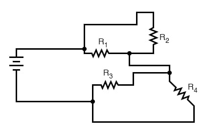
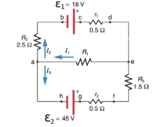
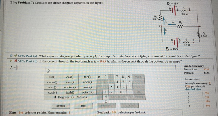
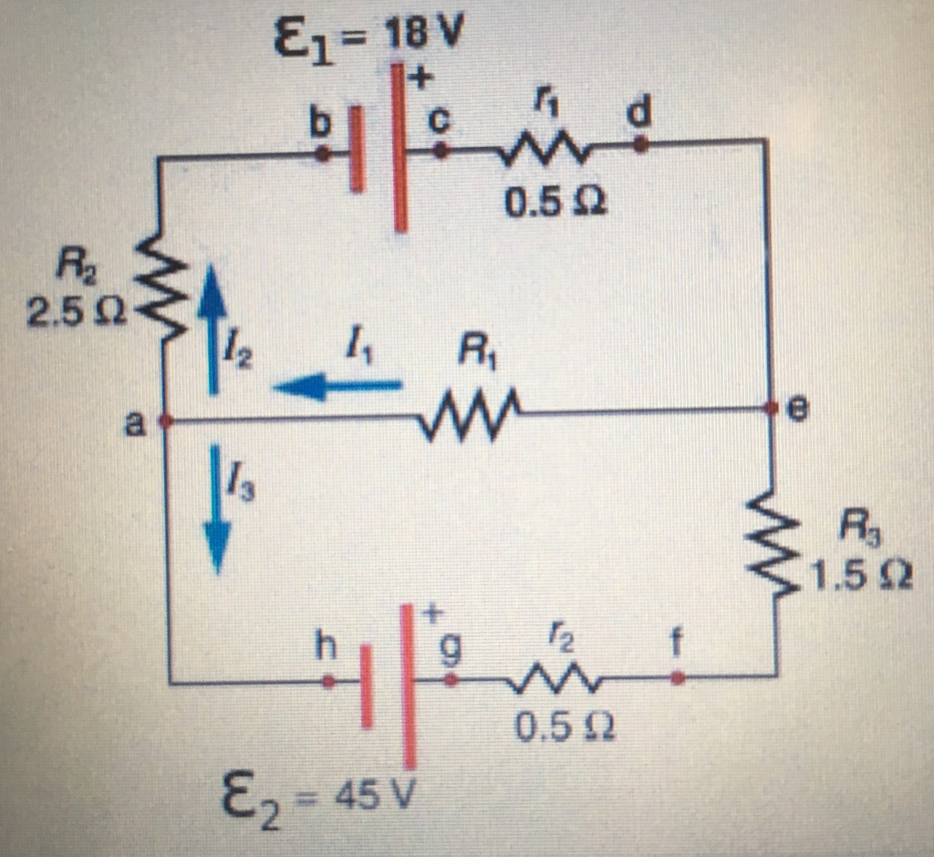
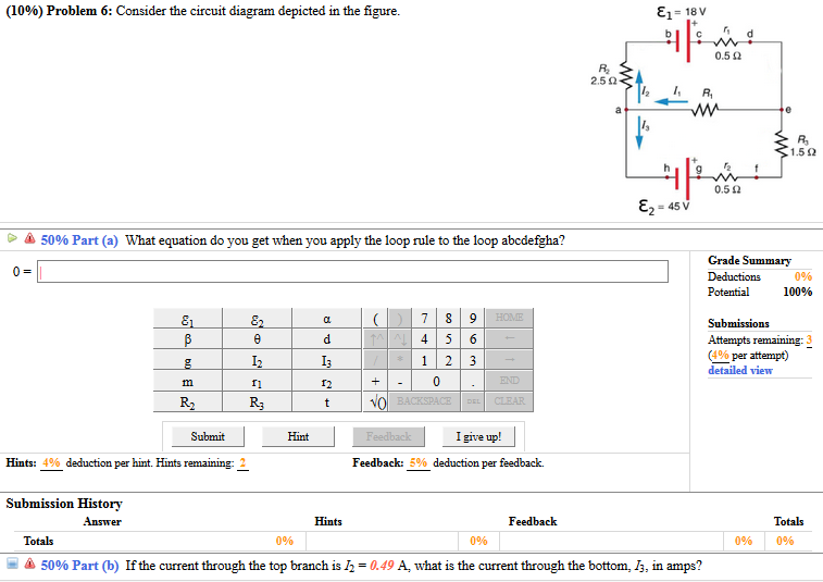
40 consider the circuit diagram depicted in the figure

Electronic devices and circuit theory (robert boylestad)(1) Nilan Lakmal. Download Download PDF. Full PDF Package Download Full PDF Package. This Paper. A short summary of this paper. 15 Full PDFs related to this paper. Read Paper. Download Download PDF. … The diagram below shows an 8-bit adder array, with the carry bits being passed along from one position to the next. Everything in electronics is modular, so if you want to add 32-bit numbers you could buy four of these components and connect them together (see Figure 10).

Consider what happens when a clean piece of copper metal is placed in a solution of silver nitrate ... Figure 1. When a clean piece ... One half-cell, normally depicted on the left side in a figure, contains the anode. Oxidation occurs at the anode. The anode is connected to the cathode in the other half-cell, often shown on the right side in a figure. Reduction occurs at the …

Consider the circuit diagram depicted in the figure

Consider the circuit diagram depicted in the figure

Figure 12.2.2 (a) Time dependence of IR (t) and VR (t) across the resistor. (b) Phasor diagram for the resistive circuit. The behavior of IR (t)and can also be represented with a phasor diagram, as shown in Figure 12.2.2(b). A phasor is a rotating vector having the following properties: VR (t) (i) length: the length corresponds to the amplitude. Phasor notation (also known as angle notation) is a mathematical notation used in electronics engineering and electrical engineering. can represent either the vector (⁡, ⁡) or the complex number ⁡ + ⁡ =, with =, both of which have magnitudes of 1. A vector whose polar coordinates are magnitude and angle is written .. The angle may be stated in degrees with an implied conversion from ... Figure 12.36 illustrates a function diagram for the MAX1402 low-power, multichannel oversampling sigma-delta analog-to-digital converter used in industry. It applies a sigma-delta modulator with a digital decimation filter to achieve 16-bit accuracy. The device offers three fully differential input channels, which can be independently programmed. It can also be configured …

Consider the circuit diagram depicted in the figure. 22.12.2021 · Now imagine that something is modified or changed. For example, consider a cable that was previously connected to a limit switch is now to be attached to a relay, thus changing from an input to an output. An industrial PC system, as depicted in Figure 2, may be changed by swapping the module assigned to this wire and modifying the software. A ... Experiment with an electronics kit! Build circuits with batteries, resistors, ideal and non-Ohmic light bulbs, fuses, and switches. Determine if everyday objects are conductors or insulators, and take measurements with an ammeter and voltmeter. View the circuit as a schematic diagram, or switch to a lifelike view. Figure 12.36 illustrates a function diagram for the MAX1402 low-power, multichannel oversampling sigma-delta analog-to-digital converter used in industry. It applies a sigma-delta modulator with a digital decimation filter to achieve 16-bit accuracy. The device offers three fully differential input channels, which can be independently programmed. It can also be configured … Phasor notation (also known as angle notation) is a mathematical notation used in electronics engineering and electrical engineering. can represent either the vector (⁡, ⁡) or the complex number ⁡ + ⁡ =, with =, both of which have magnitudes of 1. A vector whose polar coordinates are magnitude and angle is written .. The angle may be stated in degrees with an implied conversion from ...

Figure 12.2.2 (a) Time dependence of IR (t) and VR (t) across the resistor. (b) Phasor diagram for the resistive circuit. The behavior of IR (t)and can also be represented with a phasor diagram, as shown in Figure 12.2.2(b). A phasor is a rotating vector having the following properties: VR (t) (i) length: the length corresponds to the amplitude.
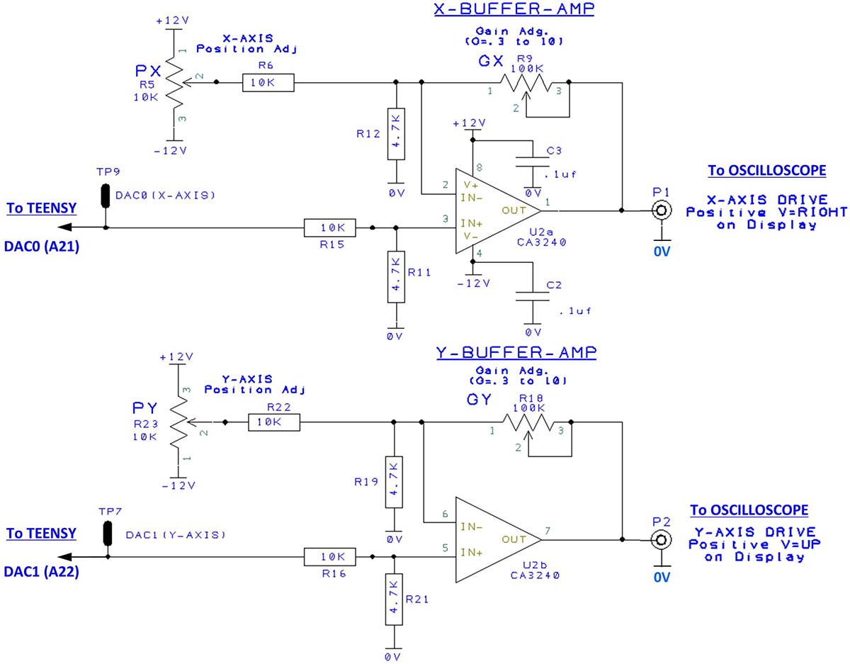
Circuit diagram of the home-made overdrive effect pedal ...

Circuit diagram of the home-made overdrive effect pedal ...

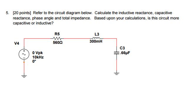
Solved: Refer To The Circuit Diagram Below. Calculate The ...

Solved: Refer To The Circuit Diagram Below. Calculate The ...

The equivalent circuit of the single-diode model ...

The equivalent circuit of the single-diode model ...

27 Consider The Circuit Diagram Depicted In The Figure ...

27 Consider The Circuit Diagram Depicted In The Figure ...

Consider The Circuit Diagram Depicted In The Figure ...

Consider The Circuit Diagram Depicted In The Figure ...

Consider The Circuit Diagram In The Figure - General ...

Consider The Circuit Diagram In The Figure - General ...

Consider The Circuit Diagram Depicted In The Figure ...

Consider The Circuit Diagram Depicted In The Figure ...

Consider The Circuit Diagram Depicted In The Figure ...

Consider The Circuit Diagram Depicted In The Figure ...

Audi WEC No.7

Audi WEC No.7

Consider the automobile speed control system depicted in ...

Consider the automobile speed control system depicted in ...

Consider The Circuit Diagram Depicted In The Figure ...

Consider The Circuit Diagram Depicted In The Figure ...

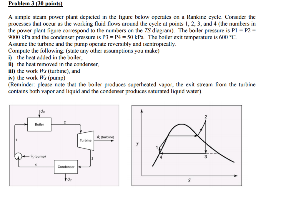
Solved: A Simple Steam Power Plant Depicted In The Figure ...

Solved: A Simple Steam Power Plant Depicted In The Figure ...

Red Porsche GT4 at Circuit Paul Ricard (french track) - 3

Red Porsche GT4 at Circuit Paul Ricard (french track) - 3

Consider The Circuit Diagram Depicted In The Figure - Free ...

Consider The Circuit Diagram Depicted In The Figure - Free ...

Consider The Circuit Diagram Depicted In The Figure ...

Consider The Circuit Diagram Depicted In The Figure ...

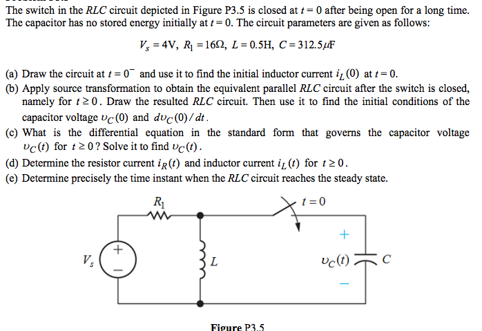
Solved: The Switch In The RLC Circuit Depicted In Figure P ...

Solved: The Switch In The RLC Circuit Depicted In Figure P ...

27 Consider The Circuit Diagram Depicted In The Figure ...

27 Consider The Circuit Diagram Depicted In The Figure ...

27 Consider The Circuit Diagram Depicted In The Figure ...

27 Consider The Circuit Diagram Depicted In The Figure ...

Consider The Circuit Diagram In The Figure - General ...

Consider The Circuit Diagram In The Figure - General ...

Consider The Circuit Diagram Depicted In The Figure ...

Consider The Circuit Diagram Depicted In The Figure ...

Consider The Circuit Diagram Depicted In The Figure - Free ...

Consider The Circuit Diagram Depicted In The Figure - Free ...

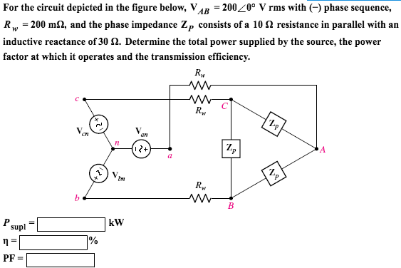
Solved: For The Circuit Depicted In The Figure Below, V_AB ...

Solved: For The Circuit Depicted In The Figure Below, V_AB ...

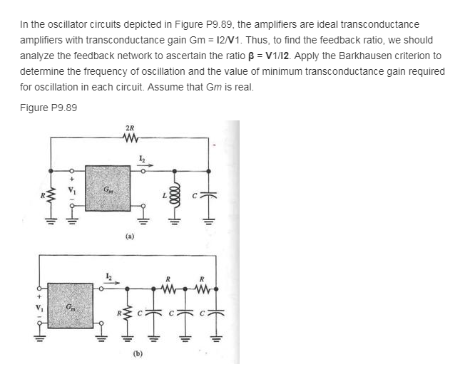
Solved: In The Oscillator Circuits Depicted In Figure P9.8 ...

Solved: In The Oscillator Circuits Depicted In Figure P9.8 ...

Ivoted2015

Ivoted2015

Quantum circuit implementing Shor's algorithm for period ...

Quantum circuit implementing Shor's algorithm for period ...

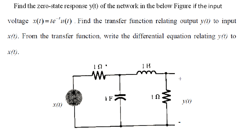
Solved: For The Circuit Depicted In Fig. P 1.8-1. Find The ...

Solved: For The Circuit Depicted In Fig. P 1.8-1. Find The ...

Consider The Circuit Diagram Depicted In The Figure - Free ...

Consider The Circuit Diagram Depicted In The Figure - Free ...

Circuit de Spa-Francorchamps

Circuit de Spa-Francorchamps

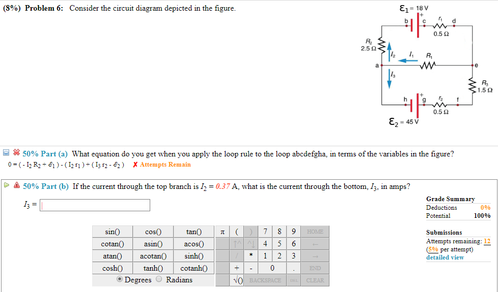
Solved: Consider The Circuit Diagram Depicted In The Figur ...

Solved: Consider The Circuit Diagram Depicted In The Figur ...

Consider The Circuit Diagram Depicted In The Figure - Free ...

Consider The Circuit Diagram Depicted In The Figure - Free ...

One side of the Janus Figure in late summer 2013.

One side of the Janus Figure in late summer 2013.

27 Consider The Circuit Diagram Depicted In The Figure ...

27 Consider The Circuit Diagram Depicted In The Figure ...

Consider The Circuit Diagram Depicted In The Figure ...

Consider The Circuit Diagram Depicted In The Figure ...

The Stone Man

The Stone Man

7 Consider The Circuit Diagram Depicted In The Figure ...

7 Consider The Circuit Diagram Depicted In The Figure ...

Consider The Circuit Diagram Depicted In The Figure - Free ...

Consider The Circuit Diagram Depicted In The Figure - Free ...

Solved: Consider The Circuit Diagram Depicted In The Figur ...

Solved: Consider The Circuit Diagram Depicted In The Figur ...

Schematic diagram of the Stirling heat engine cycle ...

Schematic diagram of the Stirling heat engine cycle ...

WD-40 Rider no. 31 on a bend at Silverstone

WD-40 Rider no. 31 on a bend at Silverstone

Consider The Circuit Diagram Depicted In The Figure - Free ...

Consider The Circuit Diagram Depicted In The Figure - Free ...

0 Response to "40 consider the circuit diagram depicted in the figure"

Post a Comment

Iklan Atas Artikel

Iklan Tengah Artikel 1

Iklan Tengah Artikel 2

Iklan Bawah Artikel