38 powerflex 525 wiring diagram
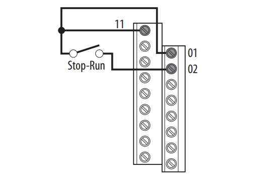
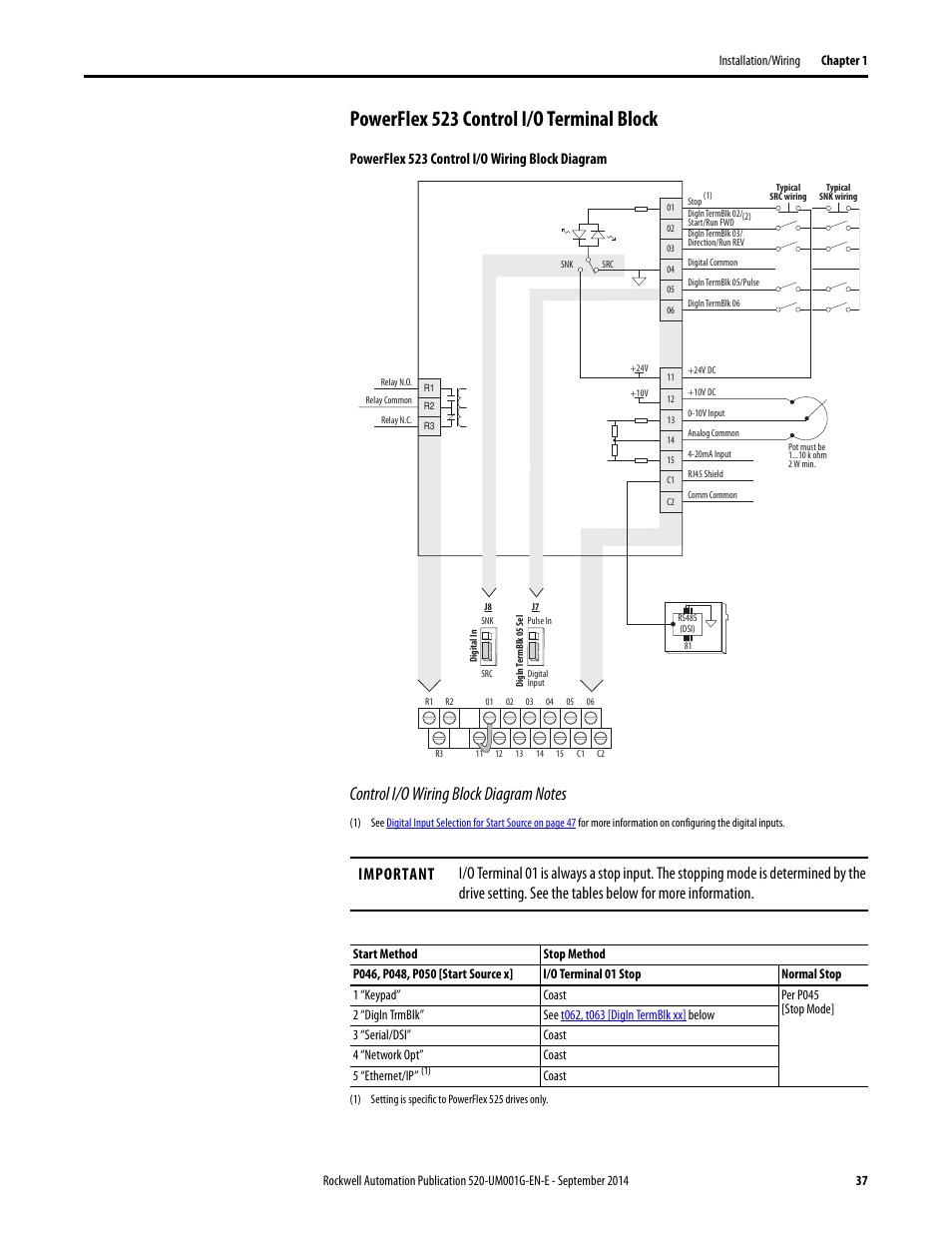
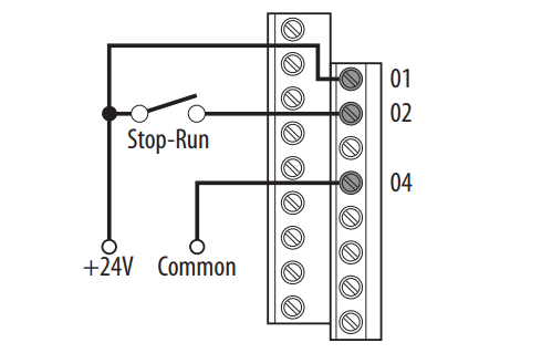
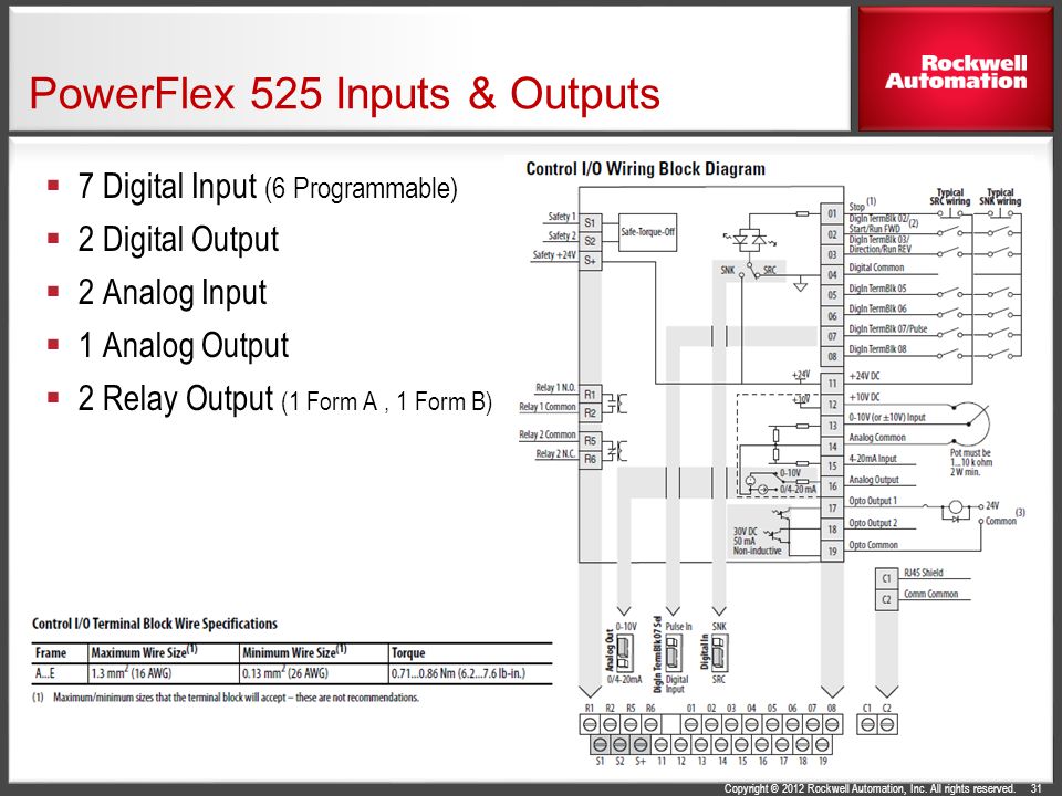
- info -Nui. aims at the concept 'Beyond all borders'. On the 1st floor, cafe& bar lounge, our guests and Japanese local people come and look forward to coff... Follow these steps to download the files for your PowerFlex 525 drive. 1. Go to the Rockwell Automation ... PowerFlex 525 Control I/O Wiring Block Diagram.
Page 173: Network Wiring PowerFlex 525 drives support the RS485 (DSI) protocol to allow efficient operation with Rockwell Automation peripherals. In addition, some Modbus functions are supported to allow simple networking. PowerFlex 525 drives can be multi-dropped on an RS485 network using Modbus protocol in RTU mode. Page 174: Parameter ...

Powerflex 525 wiring diagram
Further information can be found in the PowerFlex 525 user manual 520-UM001 of ... The precise knowledge of the operating instructions, wiring diagram, and.25 pages Wiring Diagram Next Generation Guardmaster Safety Relay (GSR) Bulletin 440R ... 6 SI E-stop PowerFlex 525 2 3 d 0 8 SI Multifunctional Access Box (MAB) PowerFlex 525 ... PowerFlex 525 Variable Frequency Drive Basic Wiring and Parameters. PowerFlex 525 VFD DataSheet: Click Here. Within the datasheet, the user will find a lot of information about the setup of the drive. This includes wiring diagrams as well as parameters which we will be setting up shortly.
Powerflex 525 wiring diagram. Oct 01, 2019 · 宝塚の広告企画会社クルーズが年に4回発行している地域コミュニティ情報誌ComiPa!(コミパ!)
宝塚市のグルメやお稽古、街の素敵な情報を発信!
情報提供してくださる方・バナー広告主様も募集中です‼ PowerFlex® 525 is controlling a motor that is considered the hazard. A selector switch requests access to the hazard area. A push button locks access to the hazard. The CR30 safety relay performs the logic that monitors the interlock and the drive, and allows access to the hazard under safe conditions. Page 33 ATTENTION: Due to its control circuitry difference from the PowerFlex 523 and PowerFlex 525 drives, connecting Terminals 01 and 11 on the PowerFlex 527 drive causes an internal short and results in some internal components incurring damage to the control module I/O circuitry. PowerFlex 525 Variable Frequency Drive Basic Wiring and Parameters. PowerFlex 525 VFD DataSheet: Click Here. Within the datasheet, the user will find a lot of information about the setup of the drive. This includes wiring diagrams as well as parameters which we will be setting up shortly.
Wiring Diagram Next Generation Guardmaster Safety Relay (GSR) Bulletin 440R ... 6 SI E-stop PowerFlex 525 2 3 d 0 8 SI Multifunctional Access Box (MAB) PowerFlex 525 ... Further information can be found in the PowerFlex 525 user manual 520-UM001 of ... The precise knowledge of the operating instructions, wiring diagram, and.25 pages







0 Response to "38 powerflex 525 wiring diagram"
Post a Comment