38 arcade button wiring diagram
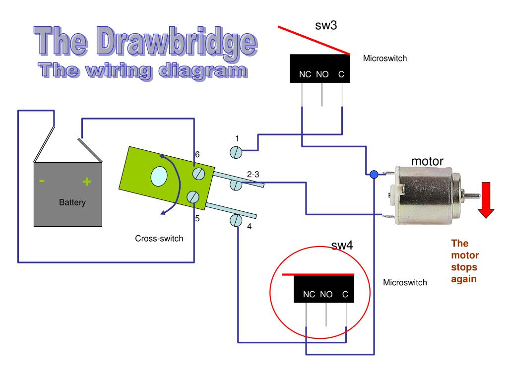
What you want to do is similar to wiring the 3-tab rocker switch in a fused IEC power inlet. - It's a different application, but basicly the same idea. Recoil power "+" (24v?) comes in on tab 8. When the switch is in the "on" (closed) position recoil power is applied to the current-limiting resistor + lamp and it goes out on tab 7 to the gun. April 29, 2018 - Hey guys, so I am in the middle of making my arcade and I just got delivered the button... and I know how to get the button to work but don't know how to get the Led to work. These are Led Arcade buttons if you didn't know, here they are: Also here is th...
If you want a more simple setup, use this wiring diagram with the indicated changes. Quote from: PL1 on January 24, 2021, 06:58:29 pm If you want to add a "Neutral" switch and LED indicator to the wiring-only diagram, insert an SPDT switch between ground and switch 3 "IN".
Arcade button wiring diagram
Repeat this process for each potentiometer leg and arcade button leg, referring to the wiring diagram. Not every joint will be the same, so make sure you know what wire needs to go where. Don't solder anything to the bottom right most arcade button (on pin 13) as it's quite different and covered in the next section. Circuit Diagram - VERTER. In this circuit all of the components are connected to VERTER. The pins are labeled on the PCB and make it easy to wire up. This provides a visual reference for wiring of the components. They aren't true to scale, just meant to be used as reference. 9V Battery negative (black wire) to VIN- on VERTER. This video is for those that are new to wiring arcade buttons. Here I will show you how a zero delay encoder is wired to the arcade buttons, joystick and oth...
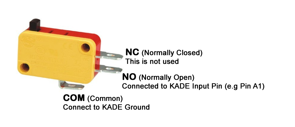
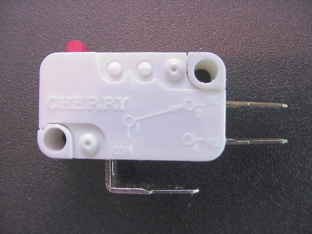
Arcade button wiring diagram. In this video we will walk through the different button layouts and a wiring basics overview for your arcade machine. There are several different layouts th... Jul 03, 2009 · The most common wiring setup for a microswitch is to have the ground wire on the very bottom prong (the common prong) and the action wire on the prong closest to the ground wire (the normally open prong). This will send a signal to the board whenever the button is pressed. This setup is used in the majority of arcade games that you will encounter. Secure PCB Mount to Top Cover. Position the PCB mount in place and line up the M3 standoffs with the mounting holes in the top cover. While holding in place, insert and fasten the 4x M3x4mm long screws to secure the PCB mount to the top cover. Get arcade wire led button with free return and fast delivery. The arcade wire led button is suitable for diy and home diy projects.
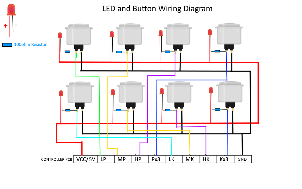
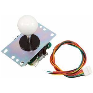
Mar 14, 2018 · Led arcade button wiring diagram. One of the things that made it easy to wire the buttons was the fact that i used the mot ion controller as opposed to a programmable interface board like the ipac. What ever power supply you use the principal is the same. For anything more well have to manually solder them. I got this Arcade button starter kit that came with two sets of buttons and joysticks. You can get single-player kits as well. Be sure to get a kit that provides a USB controller board, as this will save a lot of time from having to do custom wiring work. There are a lot of styles with arcade buttons. We can change the number of pins, their wiring, and what key-codes they send. Open up the main.py file in your favorite text editor and take a look at the code. If you want to change the pins for the buttons, look for the buttonpins list variable: # The button pins we'll use, each will have an internal pullup buttonpins = [D12, D11, D10, D9, D6 ... Adafruit Arcade Bonnet. This cute little bonnet is designed for quickly adding arcade buttons to your Raspberry Pi. It has six JST connectors that are compatible with our arcade button quick connect wires, so no soldering required. There's also dedicated pins for wiring up an analog joystick and an 8-way switch joystick.
July 29, 2002 - Build your own genuine arcade controls to play your favorite game on your PC. Reviews of ready made arcade consoles and other various things. Here are a number of highest rated 2 Player Arcade Button Layout pictures on internet. We identified it from well-behaved source. Its submitted by handing out in the best field. We recognize this kind of 2 Player Arcade Button Layout graphic could possibly be the most trending subject considering we part it in google help or facebook. How To Replace Your Pc S Power Button With An Arcade Pushbutton Arcade Power Button Arcade Cabinet . Pin By Cesar Alejandro On Saint Seiya Power Computer Internet Hard Disk . ... Best 12v Relay Wiring Diagram Pin At Switch 5 How To Wire A Electrical Diagram Circuit Diagram Relay . June 15, 2016 - So you've just received your Zero Delay Arcade USB Encoder and its time to wire it up! Start by getting the USB Encoder PCB board and take note of the connections. We are going to wire up the Joystick first, so grab that and the ribbon cable. Plug one end of the ribbon cable into the joystick ...
1995
Arcade USB Encoder Wiring Guide. Oct 19, 2011. So you've just received your Zero Delay Arcade USB Encoder and its time to wire it up! Start by getting the USB Encoder PCB board and take note of the connections. We are going to wire up the Joystick first, so grab that and the ribbon cable. Plug one end of the ribbon cable into the joystick port ...

Project MAME - Basic Arcade and MAME joystick and push ...
One of the best examples would be Buckethead's use of an arcade-style button to create a spring-loaded, momentary killswitch button rather than a switch, the signal would be killed when the button ...

Arcade Button Wiring Diagram Collection
Free delivery on millions of items with Prime. Low prices across earth's biggest selection of books, music, DVDs, electronics, computers, software, apparel & accessories, shoes, jewelry, tools & hardware, housewares, furniture, sporting goods, beauty & personal care, groceries & just about anything else.
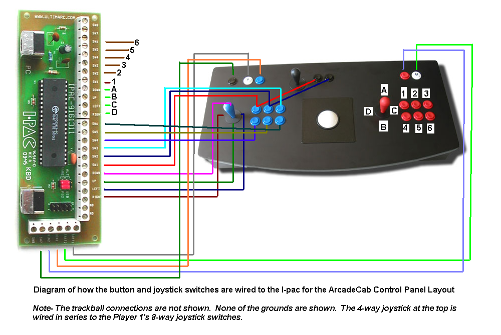
ArcadeCab- MAME Cabinet Plans 2: Wiring the Control Panel
Learn how to set up a photo booth with StealthSwitch3 using illuminated arcade buttons and non-lighted arcade push buttons with these step by step instructions.
Controls different in Attract Mode and EmulationStation ...
February 16, 2019 - X-Arcade™ BYO Kit Advanced Installation Diagram NOTE: The ground wires are all ground, so you can use any ground with any input as needed. Click to Download NOTE: Mode B is the Save/Load button for programming. Wiring pinout for Mod...
Retro Arcade Control Panel Build & Wiring | Half Ass Craftsman
Joystick Arcade Game Wiring Diagram Video Game Push-button PNG - Free Download. This PNG image was uploaded on September 29, 2018, 9:57 am by user: OnStilts ...
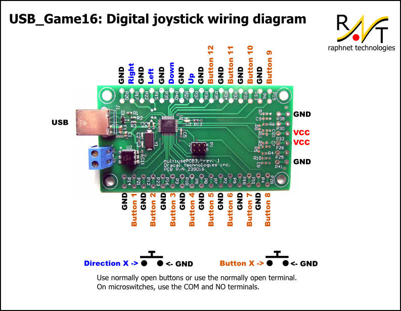
USB_Game16: Joystick controller
Free delivery on millions of items with Prime. Low prices across earth's biggest selection of books, music, DVDs, electronics, computers, software, apparel & accessories, shoes, jewelry, tools & hardware, housewares, furniture, sporting goods, beauty & personal care, groceries & just about anything else.

DIY Arcade Cabinet Kits + more. - Advanced Wiring
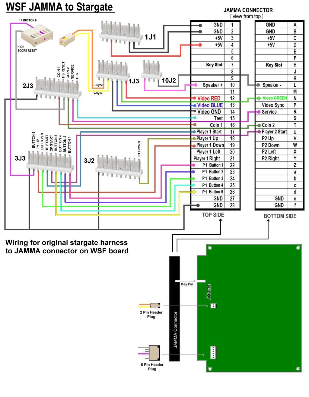
Jamma Harness Wiring Diagram. It comes with edge connector push button lugs power leads grounds and RGB monitor output connection for hookup to older. Ad Over 70 New. How to Connect a Jamma Harness. Pins 1-6 27 28 A-F e and f get wired to your switching power supply appropriately.

StealthSwitch3 Arcade Button Installation Info for DIY ...
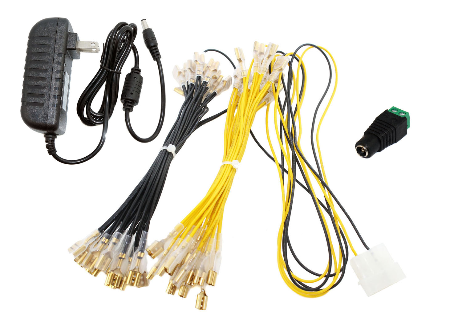
Power supply and wire kit to power the LED's on 30 LED arcade buttons with .250in/6.3mm connectors.

Wiring Dummy Arcade buttons
Diagrams JAMMA Wire Harness Map 1 Player Xin Mo Wiring Map 2 Player Xin Mo ... Arcade Power Sully Connections - IEC Switch ... 12v LED Fusion Button Wiring.
Arcade USB Encoder LED Zero Delay Arcade Controller PC PS3 ...
wiring diagram klx 150. Beranda / button / control / vector. Control Button Vector Art ... Colorful Arcade Button Set Download Free Vectors Clipart Graphics Vector Art . Vcr Dvd Player Buttons Clip Art 116238 Free Svg Download 4 Vector . Tape Deck Control Buttons Outline Clip Art 108233 Free Svg Download 4 Vector .
Arcade Button Wiring Diagram Collection
April 15, 2020 - ARCADE BUTTONS WITH LED A button is a button, and a switch is a switch, but the translucent arcade buttons are in a class of their own. Particularly because they have LEDs built in. The arcade butt…

easyget LED arcade button cable connections | Arcade games ...
This is a precise diagram of the Sega layout used in Astro City, Blast City (the bottom middle-finger button is .5mm more to the right, and the joystick is in the higher position), Net City, and Versus City cabinets for player 1 or single player.
Happ Trackball Wiring Diagram
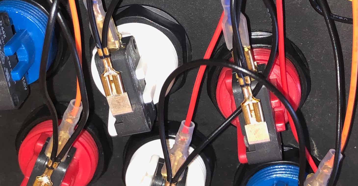
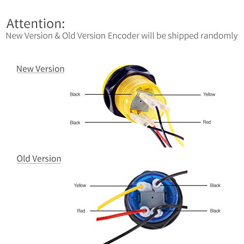
Jan 10, 2022 · Wiring the Arcade Button LED. The LED pins are the shorter pins and are placed directly below the microswitch. The pin on the left is the LED cathode (or negative wire [-]). The pin on the right is the LED anode (or positive wire [+]). NOTE: Arcade controls for decades have wired the red wire to the negative and the black wire to the positive. We don’t know why this was decided, but it is backwards from standard convention.

Arcade Button Wiring Diagram - Wiring Diagram Networks
June 28, 2017 - Make a custom control box using arcade buttons and Circuit Python.
Arcade Wire Diagram - Wiring Diagram Networks
The arcade button works through a GPIO connection. The limit switch works through a GPIO connection. ... The buzzer works through a PWM connection. Wiring. The following image displays the Fritzing Diagram for the Homemade Bop It. The Fritzing file can be downloaded at the end of the page. ... One thing I did differently was to use a ...

power - ARCADE
Basic Wiring Guide For MAME cabinets ______________________________________________________ · This is of course more simple than a two or four player encoder, but there really is no difference. There is one wire for each push button and one for each joystick direction.

Fighting Game Hardware, Strategy, Tech and More: Xbox One ...
Arcade Legends Manual Rev1.pdf. 2006-07-01 21:47. 959K. Arch Rivals Hometown Hero Options Kit.pdf. 2006-06-11 17:50. 376K. Arch Rivals Kit Installation (16-4001-K-101 May 1989).pdf.
Arcade Button Wiring Diagram - Wiring Diagram Networks
The buttons each have four connections… one is for the button feature, one powers the LED and the other two are ground. I needed to connect the button and LED connections to GPIO pins on the Pi Pico, and both grounds can be connected together than to the same ground pin on the Pico. Something like this: LED Button wiring diagram.
Microswitch Layout
157.89US $ |X 360 to arcade machine time board game kit with American joystick and button for CGA or VGA arcade machine play for time|game tft|game ...

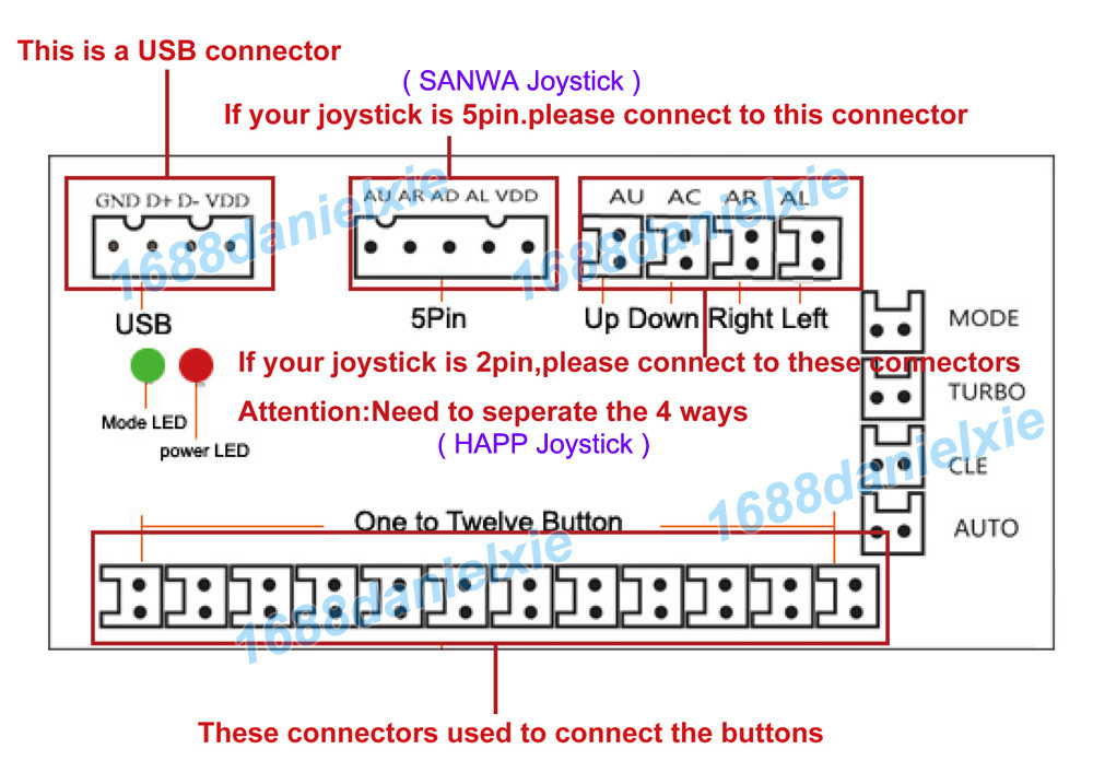
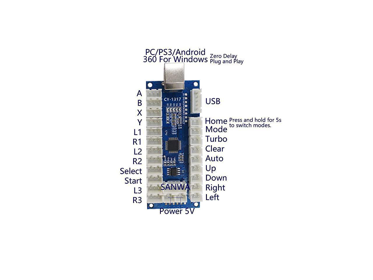
Zero Delay Arcade USB Encoder PC Joystick MAME 5Pin Sanwa ...
July 19, 2017 - Zero Delay has two (red) 2 pin 5v connectors, how to connect 10 LED buttons?.

How do I get these Led Arcade buttons to light up ...
Sorry, we just need to make sure you're not a robot. For best results, please make sure your browser is accepting cookies
Arcade Warrior (Midi Fighter Pro clone) | Tomash Ghz
Add LEDs to Your Arcade Stick Sanwa Buttons!: There are lots of LED solutions available for your fightstick or arcade cabinet but the solderless or shop-bought versions can cost quite a bit. Not being in a particularly well paid job but still wanting some LED flair to my fightstick I searched a…
Micro Switch No Nc Wiring Diagram - Wiring Diagram
June 28, 2017 - The LEDs are embedded into the arcade button housing. They appear separate in the diagram for clarity. To power this project, we're connecting microUSB to a computer's USB port. This doesn't require any external power like from a battery. D12, D11, D10, D9 from Adafruit Feather to Arcade button

Led Arcade Button Wiring Diagram Database
Arcade Button WIring [Continued] Now we can solder the second "extra" wire to the opposite lead of the arcade button. You can either thread the wire through the hole or just solder it in place. This second wire will be connected to one of the digital pins on the Trinket later. Hopefully the coloring here isn't confusing.

Arcade Button Wiring Diagram Collection
Sevcon 633t45312 Controller Wiring Schematic - 8 images - wiring diagram warning samsung dv42h5200ef a3 user,

Project MAME - Basic Arcade and MAME joystick and push ...
Circuit Diagram. This provides a visual reference for wiring of the components. They aren't true to scale, just meant to be used as reference. The LEDs are embedded into the arcade button housing. They appear separate in the diagram for clarity. To power this project, we're connecting microUSB to a computer's USB port.
Build Your Own Arcade Controls - Wiring
Its possible they wired it so two button did the same function. Like a shoot on either side of the joystick. I'm seeing exposed wire on the blue/yellow where its crimped into the connector with the blue/black so its likely that is not factory. When all else fails consult the wiring diagram in the manual.

X Arcade Wiring Diagram - Wiring Diagram Schemas
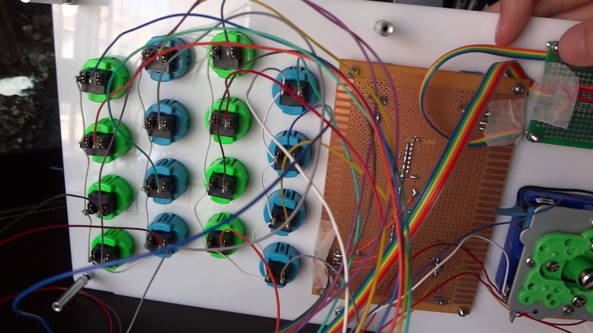
This video is for those that are new to wiring arcade buttons. Here I will show you how a zero delay encoder is wired to the arcade buttons, joystick and oth...

Arcade USB Encoder Wiring Guide- The Pi Hut
Circuit Diagram - VERTER. In this circuit all of the components are connected to VERTER. The pins are labeled on the PCB and make it easy to wire up. This provides a visual reference for wiring of the components. They aren't true to scale, just meant to be used as reference. 9V Battery negative (black wire) to VIN- on VERTER.

X Arcade Tankstick Wiring Diagram
Repeat this process for each potentiometer leg and arcade button leg, referring to the wiring diagram. Not every joint will be the same, so make sure you know what wire needs to go where. Don't solder anything to the bottom right most arcade button (on pin 13) as it's quite different and covered in the next section.

Button Wiring | Arcade Bonnet Controller | Adafruit ...

Arcade Button Wiring Diagram - Wiring Diagram Networks
Arcade Button Wiring Diagram

first time shooting with my own camera and first edit

X Arcade Wiring Diagram - Wiring Diagram Schemas
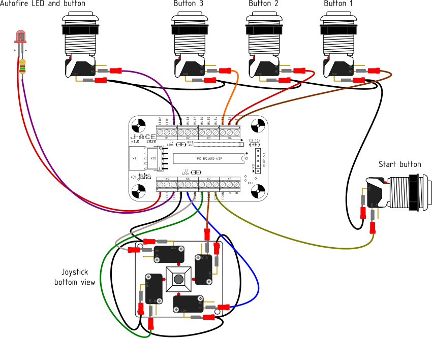
J-ACE Arcade Controls Encoder
Led Arcade Button Wiring Diagram - CINTAJUMIESHAHRIL
0 Response to "38 arcade button wiring diagram"
Post a Comment