36 gas fireplace wiring diagram
Install & Owners Manuals. Find your Heatilator product installation or owner's manual. Each fireplace and insert has a rating plate which contains your model number and serial number. Gas and wood burning fireplaces have a rating plate in the control compartment area, under the smoke shield or on the firebox side column. User Guides & Manuals. User Guides & Manuals. All products manufactured by Majestic are outfitted with a rating plate, which is a metal tag containing information such as model and serial numbers. The rating plate is found in different places, depending on the unit: Gas Fireplaces and Gas Log Sets: The rating plate is near the gas control valve ...
4 WS-415-106 /05.19.99 GENERAL INSTRUCTIONS THIS GAS FIREPLACE SHOULD BE INSTALLED AND SERVICED BY A QUALIFIED INSTALLER to conform with local codes. In absence of local codes, install to the current National Fuel Gas Code, ANSI Z223.1, or the current CAN/CGA B149,
Gas fireplace wiring diagram
This one covers the thermopile wiring on the gas fireplace. This video is part of the heating and cooling series of training videos made to accompany my web... Wiring diagrams are included for the two most common types of ignition systems found in gas fireplaces. These ignition systems include the millivolt ignition (standing pilot / continuous pilot) and the intermittent pilot ignition IPI (electronic ignition). benefit and enjoyment from your Kozy Heat gas fireplace. Jim Hussong. Dudley Hussong. President. Board Chairman. INTRODUCTION. Read this manual before ...80 pages
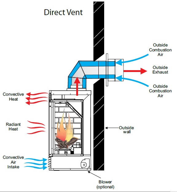
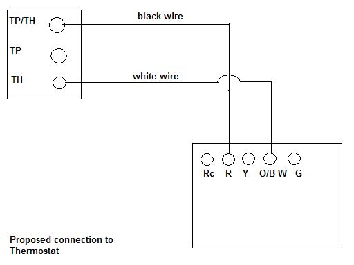
Gas fireplace wiring diagram. 2 Regency® P40-1 Direct Vent Gas Fireplace To the New Owner: Congratulations! You are the owner of a state-of-the-art Gas Fireplace by REGENCY®. The P40 has been designed to provide you with all the warmth and charm of a wood fi replace at the fl ick of a switch. The model P40 has been approved by Warnock Hersey for both safety and effi ... First, disconnect the thermostat wires from the gas fireplace -- you will use your existing thermostat wiring -- and it's always a good idea to disconnect things when working with electricity. Install the AC adapter -- I placed mine behind the wall in the laundry room (very convenient there was an outlet right there for me) and ran the wiring ... 6 Regency P48-1 Zero Clearance Direct Vent Gas Fireplace INSTALLATION Diagram 1 UNIT SPECIFICATIONS This includes: 1) Clocking the appliance to ensure the correct firing rate (rate noted on label 51,000 (NG) Btu/h, 48,000 (LP) Btu/h) after burning ap-pliance for 15 minutes. 2) If required, adjusting the primary air to en-sure that the flame ... Gas Fireplace Wiring Diagram wiring diagram is a simplified up to standard pictorial representation of an electrical circuit. The following wiring diagrams are for illustration purpose only. There are lots to handle with this device and it can be quite difficult. The diagram shows 120v coming into a 120v24v transformer and.
NOTE: Diagrams and Illustrations NOT to Scale Page 4 of 6 My Fireplace Blower Burlington, Wisconsin 1-800-466-4045 MyFireplaceBlower.com: Ground Wire (Green) WIRING NOTES: This is a polarity sensitive system. Ensure you wire it exactly as shown in the diagram above. Thermopile wires must also be located with Red at TH/TP and White at TP on the ... Blower Wiring Diagram CAUTION: Label all wires prior to disconnection when servicing controls. Wiring errors can cause improper and dan-gerous operation. Verify proper operation after servicing. FIREPLACE INSTALLATION Continued Figure 30 - Blower Wiring Diagram for Thermostat-Controlled Models Blue Variable Fan Switch Fan Switch (N.O.) Green ... Dimension: 739 x 739. DOWNLOAD. Wiring Diagram Images Detail: Name: gas fireplace wiring diagram - Gas Fireplace Instructions New Fireplace Wiring Diagram Unique 3 Ways to Light A Gas Fireplace. File Type: JPG. Source: wwewrestlemania33.com. Size: 123.23 KB. Dimension: 728 x 546. DOWNLOAD. DEXEN VALVE ELECTRONIC IGNITION NOT SPARKING DIAGNOSTICS TEST - continued. If (A) (B) (C) TEST #3 - Confirm that the wire harness connection on ignition control module is correct (see picture). STEP #1- onnect the 2 brown wires marked SWI together to confirm pilot is sparking.
Step 1: Connecting the Low Voltage Wiring. The first step is to open the bottom panel of your fireplace (mine is held on by magnets) and find the wiring which goes to the wall switch. If your installer did a good job, it will be labeled for you. If not, just look for small wires heading out of the fireplace up towards the switch. 5 Steps for Adding a Thermostat to a Gas Fireplace. Get a 24v AC Adapter. Purchase Fan Relay. Install the Nest and Connect the Wiring. Connect the Fan Relay. Plug the Ac Adapter and Connect the Nest Thermostat. Make sure all wiring is not damaged or broken and all connections are tight. Correct if necessary. By pas spill switch. If unit starts, replace spill switch. B-VENTED MODELS Check spill switch. Check to make sure the vent is drafting properly. Check for spillage. SEE PAGE 12. Make sure all venting meets manufactures specifications as well as ... To find a remote control that is compatible with your gas fireplace, the first thing you'll need to find is what type of gas valve your fireplace uses. This information can be found most easily in your fireplace installation & operation manual, the relevant information is usually located under the "Wiring Diagram". If you don't have your ...
A wiring diagram is a simplified traditional pictorial representation of an electric circuit. Much like wall furnaces gas fireplaces come on and off with a wall switch and can be controlled by a remote. Assortment of millivolt gas valve wiring diagram. Assortment of gas fireplace wiring diagram. A gas fireplace can also have a heat zone system ...
Gas Fireplace & Gas Heater Manuals, parts lists, wiring diagrams: Free downloadable manuals for LP and natural gas-fueled gas fireplaces, gas logs, gas fireplace heaters. We include links to contact information for each manufacturer or producer of these heating products and their related equipment, parts, and installation, repair, wiring ...
Jan 8, 2017 - artchinanet.com is your first and best source for all of the information you're looking for. From general topics to more of what you would expect to find here, artchinanet.com has it all. We hope you find what you are searching for!
Gas appliance diagrams, including the dimensions, are shown in this section. Pre-installation Preparation This gas insert and its components are tested and safe when installed in accordance with this Installers Guide. Report to your dealer any parts damaged in shipment, particularly the condition of the glass. Do
•Wiring Diagram for this Blower Kit is illustrated in Figure: 7. Blower operates on 120V/60Hz power. Figure: 8 CLICK CLICK CLICK Finishing Steps: If appliance is connected to a gas supply, turn it back on. If Appliance is connected to 120 Volt Power, turn it back on. Installer is responsible to check local codes
If the information in this manual is not followed exactly, a fire or explosion may result causing ... Mendota gas fireplaces are heat producing appliances.48 pages
Retain this manual for future reference. Please read this manual. BEFORE installing and operating this appliance. DV Gas Fireplace Heater. 530ILN/ILP (logs) ...48 pages
gas fireplace wiring diagram - Exactly What's Wiring Diagram? A wiring diagram is a kind of schematic which uses abstract pictorial signs to show all the interconnections of components in a system.
This is How to Wire the Thermopile to The 750mv Gas Valve for the Pilot and Main Gas Burners. This includes a WIRING DIAGRAM. I show you how to Light the Pil...
To find a remote control that is compatible with your gas fireplace, the first thing you'll need to find is what type of gas valve your fireplace uses. This information can be found most easily in your fireplace installation & operation manual , the relevant information is usually located under the "Wiring Diagram".
May 18, 2021 · 8 Steps To Install A Heatilator Gas Fireplace. Installing a Heatilator gas fireplace can be tricky. But here, it will surely get easy for you. You can rest assured that the method we are going to apply is totally authentic as we are relying on the Heatilator gas fireplace manual for the direction.
Types of Standard Fireplace Remote Controls: 1. On/Off. The most simple of all the remote control functions, this remote is as simple as it is convenient - just on and off. On/Off remotes offer reliable control in a compact design - and just like all millivolt valve remotes, they're easy to install. 2.
FK-180 Wiring-Diagram(GFK-160A).pdf FK-180-Fan Kit.pdf . Valve Kits. Skytech-AFVK-SP-AFVK-SPH-L-MH-L Manual Skytech-AFVK-AFVK-H-L-AFVK-VH-L Manual Skytech-AF-LMF-R Manual Skytech-AF-LMF Manual. Accessories. Skytech-RS-1-A-&-RS-2 Manual
A wiring diagram is a simplified traditional pictorial representation of an electric circuit. Today we ll look at the gibson les paul wiring diagram so you can use it as a reference when installing new pickups or changing a component because of wear. Assortment of gibson les paul wiring schematic. Is modern wiring better.
8000 Series Gas Fireplace UL Listing: Install Manual 8000GDV/GDVFL/GDVB. 6000DVT/8000DVT. 6000DVTFL/8000DVTFL. 8000TV. 8000TRC. SMART-STAT. 8000TVC. 6000C/8000C IPI French. 6000C/8000C & IPI Latin American Spanish. 6000CL/8000CL IPI French. 6000CL/8000CL-IPI-T & -S Latin American Spanish ...
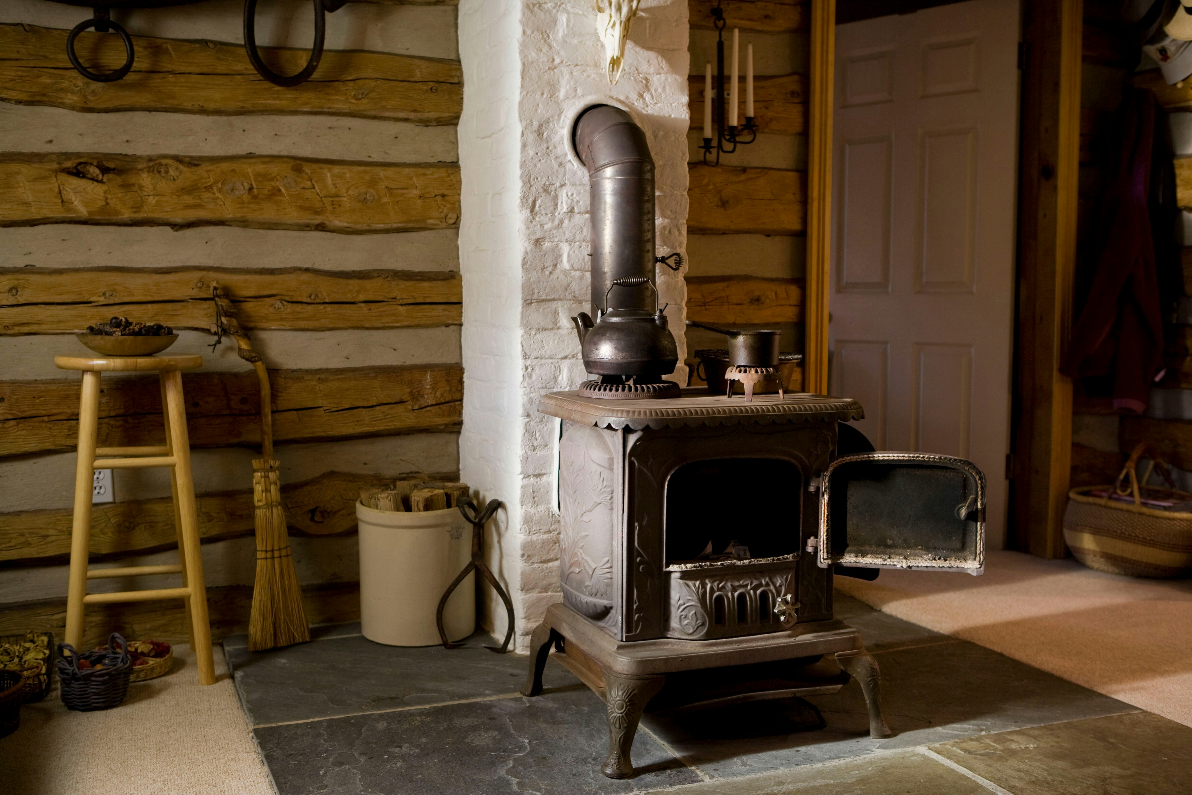
This home’s interior, though beautiful, houses a potential hazard on many levels, therefore, special care need be taken in order to safely operate this wood-burning stove, for not only does it generate a terrific amount of heat, it does so using flame, rather than electricity, which is much more difficult to control.
nologies gas fireplace, an elegant and clean alternative to wood burning fireplaces. The Hearth & Home Tech-nologies gas fireplace you have selected is designed to provide the utmost in safety, reliability, and efficiency. As the owner of a new fireplace, you'll want to read and carefully follow all of the instructions contained in this
If the pilot is lit, make sure the gas valve control is in the "ON" position. Check around the gas valve area for an "off/on" rocker switch. If found, place it in the ON position. If the burner lights, the problem is in the wiring to the wall switch. There wouldn't be any issue with circuit breakers. The wall switch connects only to the gas valve.
Gas Fireplace Replacement parts for all major brands of Gas fireplaces. All Parts in stock and ready to ship.
a gas valve, thermopile, millivolt thermostat, and a pilot Millivolt system wiring diagram.DEAN MILLIVOLT GAS FRYERS (NON-CE) CHAPTER 3: INSTALLATION INSTRUCTIONS Gas Conversion Procedures See gas valve illustration below and gas valve, burner and orifice location on page when performing the following conversions.
Oct 02, 2020 · 2008 Chevrolet Silverado Wiring Diagram from ww2.justanswer.com Print the wiring diagram off plus use highlighters to trace the signal. When you make use of your finger or perhaps the actual circuit with your eyes, it is easy to mistrace the circuit. 1 trick that We 2 to printing a similar wiring plan off twice.
tions and wiring schematics for proper placement of all wires. All electronic modules are to be wired to manufacturer's specifica-tions. The following wiring diagrams are for illustration purpose only. Follow instructions from manufacturer of gas valve and/or electronic module for correct wiring procedures.
benefit and enjoyment from your Kozy Heat gas fireplace. Jim Hussong. Dudley Hussong. President. Board Chairman. INTRODUCTION. Read this manual before ...80 pages
Wiring diagrams are included for the two most common types of ignition systems found in gas fireplaces. These ignition systems include the millivolt ignition (standing pilot / continuous pilot) and the intermittent pilot ignition IPI (electronic ignition).
This one covers the thermopile wiring on the gas fireplace. This video is part of the heating and cooling series of training videos made to accompany my web...











0 Response to "36 gas fireplace wiring diagram"
Post a Comment