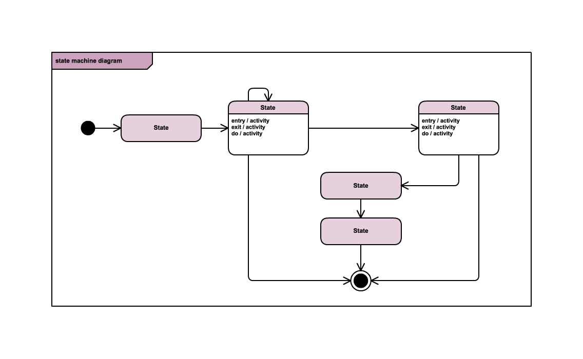
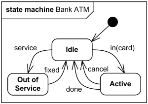
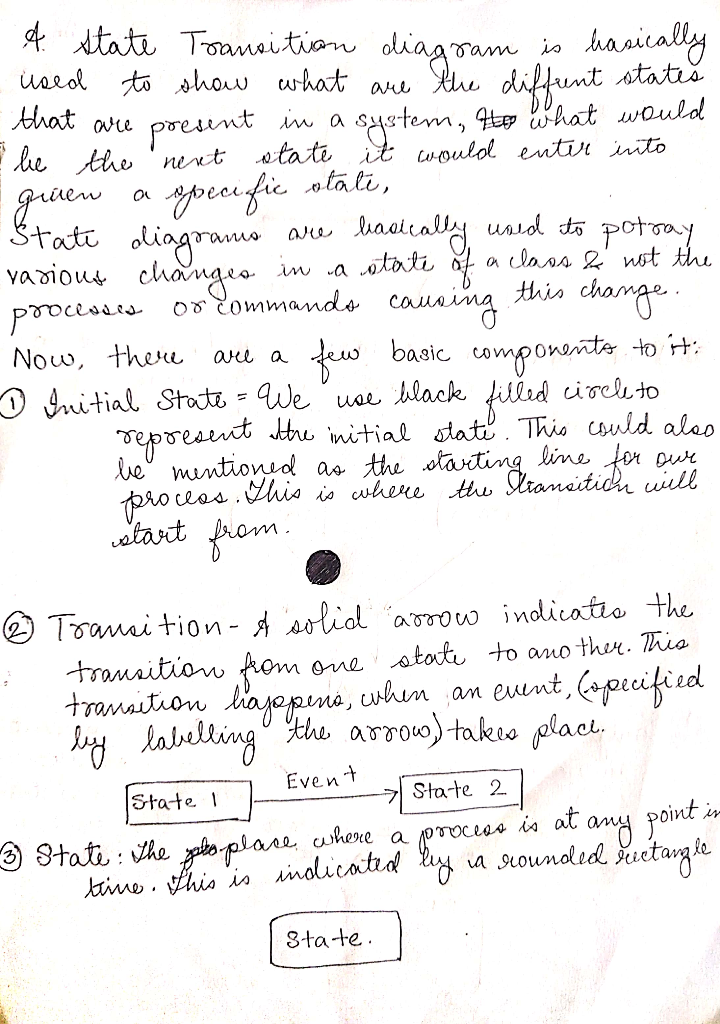
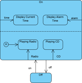
38 in a state transition diagram, the states appear as rounded rectangles with the state names inside.
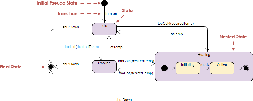
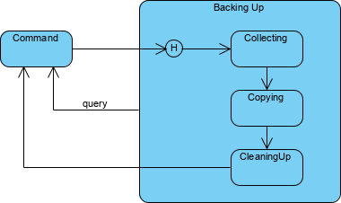
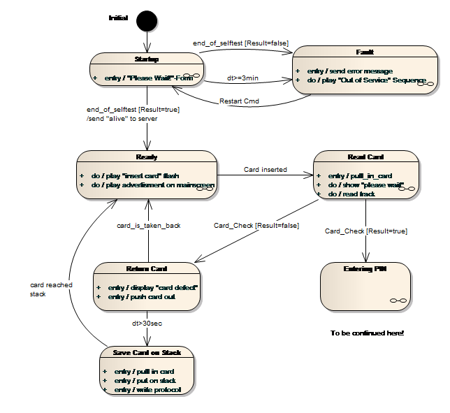
Finite state machines and their corresponding state-transition diagrams (or state diagrams for short) are the formal mechanism for collecting such fragments into a whole. State diagrams are simply directed graphs, with nodes denoting states, and arrows (labelled with the triggering events and guarding conditions) denoting transitions.
A typical phase diagram for a pure substance is shown in Figure 1. Figure 1. The physical state of a substance and its phase-transition temperatures are represented graphically in a phase diagram. To illustrate the utility of these plots, consider the phase diagram for water shown in Figure 2. Figure 2.
In a state transition diagram, the states appear as rounded rectangles with the state names inside. True In a sequence diagram, a message is identified by a narrow vertical shape that covers the lifeline.
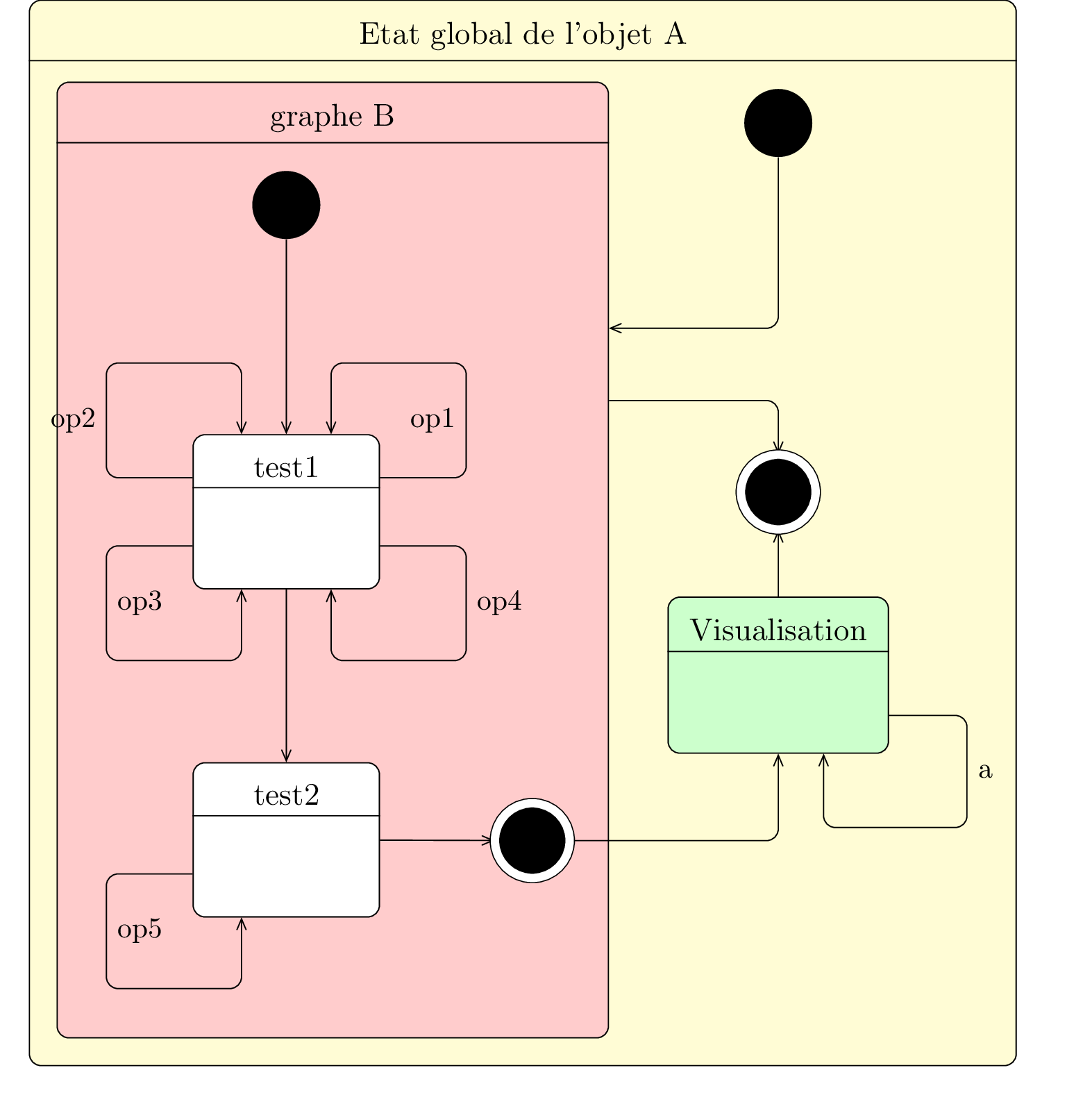
In a state transition diagram, the states appear as rounded rectangles with the state names inside.
State Machine Diagrams. State machine diagram is a behavior diagram which shows discrete behavior of a part of designed system through finite state transitions. State machine diagrams can also be used to express the usage protocol of part of a system. Two kinds of state machines defined in UML 2.4 are . behavioral state machine, and; protocol state machine
In a state transition diagram,the states appear as rounded rectangles with the state names inside. In a state transition diagram,the states appear as rounded rectangles with the state names inside. Categories Questions. Leave a Reply Cancel reply.
In a state transition diagram, the states appear as rounded rectangles with the state names inside.A) TrueB) False A) True ____ are especially important to a systems analyst who must work with people at all organizational levels, balance conflicting needs of users, and communicate effectively.A) Analytical skillsB) Artistic skillsC ...
In a state transition diagram, the states appear as rounded rectangles with the state names inside..
A transition between one state into another state occurs because of some triggered event. To draw a state diagram in UML, one must identify all the possible states of any particular entity. The purpose of these UML diagrams is to represent states of a system. States plays a vital role in state transition diagrams.
- A betting round occurs, followed by dealing 3 shared cards from the deck. - As shared cards are dealt, more betting rounds occur, where each player can fold, check, or raise. - At the end of a round, if more than one player is remaining, players' hands are compared, and the best hand wins the pot of all chips bet so far.
The UML state diagrams are directed graphs in which nodes denote states and connectors denote state transitions. For example, Figure 1 shows a UML state diagram corresponding to the computer keyboard state machine. In UML, states are represented as rounded rectangles labeled with state names.
Dec 09, 2021 · 14+ Transition State Diagram. In a state transition diagram, the states appear as rounded rectangles with the state names inside. I tried to remove but table statements needs the values to be of the same. TCP state-transition diagram | Download Scientific Diagram from www.researchgate.net A state machine diagram models the…
shows how an object changes from one state to another, depending on events that affect the object. All possible states must be documented in the state transition diagram. - Ex. bank account can be opened as NEW then changed to ACTIVE or EXISTING, then be CLOSED or FROZEN - states appear as rounded rectangles with state names inside
It is a situation occurring for a finite time period in the lifetime of an object, in which it fulfils certain conditions, performs certain activities, or waits for certain events to occur. In state transition diagrams, a state is represented by rounded rectangles. Parts of a state. Name − A string differentiates one state from another. A ...
How to draw a state diagram. Each diagram usually begins with a dark circle that represents the initial state and ends with a bordered circle that represents the final state. States are denoted with rectangles with rounded corners. Each rectangle is labeled with the name of the state. And transitions are marked with arrows that link one state ...
Inheritance In a state transition diagram, the states appear as rounded rectangles with the state names inside. True In a sequence diagram, a message is identified by a narrow vertical shape that covers the lifeline. False To create use cases, you start by reviewing the information that you gathered during the requirements modeling phase. True
Fals e ANSWER: True RATIONALE: In a state transition diagram, the states appear as rounded rectangles with the state names inside. POINTS: 1 DIFFICULTY: Moderate REFERENCES: 193 QUESTION TY PE: True / False HAS VARIABL ES: False LEARNING OB JECTIVES: SAD.12e.06.09 - Demonstrate use of the UML to describe object- oriented systems, including use ...
In a state transition diagram, the states appear as rounded rectangles with the state names inside. asked Aug 11, 2019 in Computer Science & Information Technology by phviking11 Answer the following statement true (T) or false (F)
Question 82 Complete Mark 1.00 out of 1.00 Flag question Question text In a state transition diagram, the states appear as rounded rectangles with the state names inside. Select one: True
In a state transition diagram, the states appear as rounded rectangles with the state names inside. True Inheritance enables an object, called a _____, to derive one or more of its attributes from a parent.
In a state transition diagram, the states appear as rounded rectangles with the state names inside. Symbols used in State Transition Diagram Terminologies of State Transition Diagram State In the state transition diagram, An object always remains in some state. Further, the state of the object may change after an event occur. Event
From each state comes a complete set of transitions that determine the subsequent state. States are rounded rectangles. Transitions are arrows from one state to another. Events or conditions that trigger transitions are written beside the arrows. Our diagram has two self-transition, one on Getting SSN and another on Getting PIN.
Question 2 4 out of 4 points In a sequence diagram, classes that send or receive messages are shown at the bottom of the diagram. Selected Answer: False Correct Answer: False Question 3 4 out of 4 points In a state transition diagram, the states appear as rounded rectangles with the state names inside.
The concept of State is a very effective mechanism of decomposing event-driven behavior.States divide the overall behavior of a class into separate parts, each part (state) handling events in a specific way. Any change in handling of any event requires a change of state, that is, a state transition.States are represented in UML as rounded-corner rectangles with the state name at the top.
In a state transition diagram, the states appear as rounded rectangles with the state names inside. T 22. In a state transition diagram, the circle to the left is the final state. F 23. A class diagram resembles a horizontal flowchart that shows the actions and events as they occur. F 24.
- State diagrams: A chart that contains State(s) - Flow charts: A chart that does not use State(s), only transitions and conditional logic. NOTES: most Stateflow charts use a mixture of State diagrams and Flow Charts Stateflow Semantics: rules that define how the charts are evaluated Mealy, Moore, "Classic" Stateflow
state transition diagram d. activity diagram. ... In a state transition diagram, the states appear as rounded rectangles with the state names inside. True False. True. A _____ is a visual summary of several related use cases within a system or subsystem. a.
In a state transition diagram, the states appear as rounded rectangles with the state names inside. actor In a use case, an external entity, called a(n) _____, initiates a use case by requesting the system to perform a function or process.

State diagrams a state diagram is a graph whose nodes are states and whose directed arcs are transitions between states. a state diagram specifies the.
State-Transition Diagram Components. There are two major components for this diagram: States, Changes of State, and Conditions and Actions. · System States are represented by rectangles. States are the sets of circumstances or attributes characterizing a person or thing at a given time.
From each state comes a complete set of transitions that determine the subsequent state. Hide image. States are rounded rectangles. Transitions are arrows from one state to another. Events or conditions that trigger transitions are written beside the arrows. Our diagram has two self-transition, one on Getting SSN and another on Getting PIN.
5/16/2015 12 FIGURE 6-33 An example of a state transition diagram for a bank account State Transition Diagrams Shows how an object changes from one state to another, depending on events that affect the object All possible states must be documented in the state transition diagram States appear as rounded rectangles with the state names inside CIS 2321 Summer 2015 FIGURE 6-34 An activity diagram ...
In a state transition diagram, the states appear as rounded rectangles with the state names inside. Q 10 A class diagram resembles a horizontal flowchart that shows the actions and events as they occur.
UML Activity Diagrams Reference. Notation. Description. Activity. Online Shopping activity. Activity is parameterized behavior represented as coordinated flow of actions . Activity could be rendered as round-cornered rectangle with activity name in the upper left corner and nodes and edges of the activity inside.
b. rounded rectangles. In a state transition diagram, the states appear as _____ with the state names inside. a. triangles b. rounded rectangles c. squares d. circles. c. activity. A(n) _____ diagram resembles a horizontal flowchart that shows the actions and events as they occur.
Activity Diagram: Example 55. State Transition Diagrams • Fancy version of a DFA • Shows the possible states of the object and the transitions that cause a change in state - i.e. how incoming calls change the state • Notation - States are rounded rectangles - Transitions are arrows from one state to another.


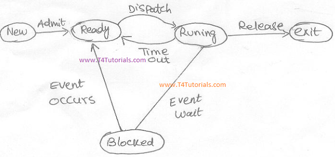
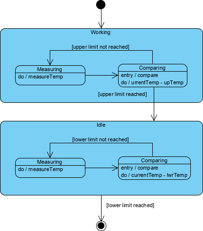


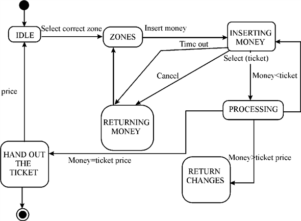









0 Response to "38 in a state transition diagram, the states appear as rounded rectangles with the state names inside."
Post a Comment