38 ford 302 coolant flow diagram
Ford 302 Cooling System. Thread starter Richard_Knight; Start date Feb 14, 2005; R. Richard Knight. Feb 14, 2005 #1 Hi, Does anyone have a diagram showing the flow of coolant around the engine / radiator etc. I have a 302 engine and the two small outlets on the water pump have been bridged - I assume these were for the heater matrix, and at the ... Build a spirited roadster with an iconic Ford 302 crate engine, achieve superior V8 power with a 7. 3 seconds. Everything you need in one place from fuel system components to water pumps. Toggle menu. Parts Diagrams & Lookups by Category. 00 Select options. To As for the GT-R Track Edition's power, Nissan has kept the turbocharged 3. We have below an exploded view of the 6. [ { "catentry_id ...
تدفق مبرد المحرك وكيفيه عمله
Ford 302 coolant flow diagram
Visit site. Jul 23, 2004. #2. Originates (pushes) at the water pump, flows through the heater core, back to the intake manifold. Note: at the manifold the heater inlet sits next to the engine outlet. Movement of water through the manifold and into the radiator causes a small vaccuum at the heater return line (it sucks)! The water flow on all small block fords is the same. In the water pump through the lower hose. Through the block (with trace amounts going to the head through the holes through the head gasket. At the back of the block the water flows through 2 big holes up into the head Then the water flows forward through the heads. The engine antifreeze/coolant usage noted in the chart above applies to all engine types (e.g., gasoline and diesel) available for a particular vehicle. G = Green-colored engine coolant approved to Ford specification ESE-M97B44-A (Motorcraft ® Premium Antifreeze/Coolant)
Ford 302 coolant flow diagram. Hi all, Does anybody have or know where there is a diagram of how the 302 H.O. motor cooling system works? If I remember correctly the flow is from the top hose down through the system and back around, or is it the other way? Judging by the way the thermostat looks, I'd say antifreeze flows... Water flow direction in radiator. Replaced water pump on 2010 f-150 4.6 3V engine. Pump has no. connection for radiator hose. Upper hose connects to thermostat housing, and lower hose connects to block at bottom of engine on drivers side. So, Vacuum Diagram As Well 2001 Ford F 150 5 4 Vacuum Line Diagrams On, size: 800 x 600 px, source: www. Sep 26, 2009 · 6. Sep 21, 2021 · Backfiring occurs when unburned fuel exits the cylinder on the exhaust stroke and is then ignited farther in the system by the spark of the next cylinder. I have put in new points and condensor, and rebuilt the carb will all Oct 08, 2009 · Well guys, the '96 ... It illustrates what happened in 1970 on all Ford small-block V-8s: Ford went to a true crossflow cooling system, which meant moving the water pump inlet to the driver's side of the engine. You must have a compatible timing cover to go with the 1970-up crossflow water pump on all 302/351W small-block Fords.
I have a 351W based 408 using the 289/302 style water pump, but I'm wondering if anyone has reversed the flow of their coolant so that the ... COOLING SYSTEM DIAGRAM? ANYBODY GOT ONE | FORD MUSTANG FORUMS. 2008-08-20 · The cooling system operates as follows: l Coolant flows through the radiator tubes ... Engines cooling systems acting odd, somewhat like a blown head gasket, yeat no water/steam seen in exhaust, and none in oil. Im wondering the direction of water flow. By looking at the pump and the fan direction, Im thinking the water goes IN at the intake and pumps out from the waterpump, pushing the water UP through the radiator. They mentioned that even as little as a 3-4 degree temperature difference (using the old Windsor design FRPP block and Yates heads) played havoc with hp creation, cylinder to cylinder timing, etc. The new engine was designed with water jackets and overall coolant flow to have zero difference between all eight cylinders.
When you're planning an engine build, plan for improved coolant flow via a high-flow water pump. Here are two examples of small-block Ford water pumps. On the left is a right-hand inlet water pump for the 221/260/289/302 prior to 1970. PrevNext. how to replace f150 heater hoses heater hoses on the ford f150 carry engine coolant to and from the heater core for use in providing heat to the passenger cabin over time these hoses. Ford F 150 Cooling System Diagram Awesome 2000 F 150 4 2 V6 Hose Help ford. 1998 ford f 150 engine diagram vacuum hose ford f150 heater hose diagram ... Hi, Does anybody have a layout revealing the flow of coolant around the engine/ radiator and so on . Early liquid-cooled engines bordered their ... 1983 - 2012 Ranger & B-Series - Coolant flow diagram - 1985 Ranger 2.8L V6. I have had recuring overheating problems. I have flushed the system twice, ...
Coolant Flow Radiator And Engine Block Below is an explanation of this system's operation The Thermostat Just like your body needs to warm up when you begin to exercise, your car's engine needs to warm up when it starts its exercise. The thermostat provides control for your engine's warm-up period.
The truck is a 1994 Ford F150 with the I6 300 engine. He's had if for about 4 months, before that it sat for a long while (not sure how long). It's got just over 200K miles. So the problems are it overheats, the overflow tank boils over (sometimes after the truck is turned off), and the heater has stopped working (same time).
Cooling system problem/water pump
Has a bad timing chain cover that leaked coolant into the oil. 5 - 1 comp PTS538A3 From 1971 to 1972 Jeep pickups offered the AMC 304 cu in (5. Regular price . oem amc jeep 304 v8 intake manifold 2 bbl. engine parts. (Dallas) Intake manifold from a 1979 CJ 7 with an AMC 304 engine. 0Negotiable. 6. Good used AMC V8 coil bracket. Finally, we illustrate how 304 Å images can be used as a proxy ...
The Ford engineers supplied a larger mass air flow meter which was the same size as the '93 Cobra. Pushrod discontinuation With Ford making the switch to the 4.6-liter modular engines in 1996 for the Mustang, they did produce the 302 up until 2001 which was an engine option in the Ford Explorer and standard in the Mercury Mountaineer.
#302. Sumit kumar (Monday, 28 June 2021 03:13) Mazda323 wiring diagram #301. Sumit kumar (Monday, 28 June 2021 03:11) Need car wiring diagram #300. Randy Thompson (Saturday, 19 June 2021 23:34) I love your forum. Only if they were more clear. I would pay or donate modest towards more higher definition scans or pdf's. Please keep up the good work. This is what life is about to share …
6,540 Posts. #2 · Jan 16, 2002. Jesmol, I think the XG has the same engine/gear as the EBII/ED sedan. If so that from memory the therostat housing is different, not sure if thats going to effect flow direction. Just out of interest what part number thermostat did you use. I got Ford part no. ART-92-G for my dads EL and it specified a flow ...
Coolant Flow Path It is important to understand how the coolant flows through the system from one component to the next. These descriptions are directed to V-8 engines in particular, but basic commonality applies to the 6-cylinder engines also. Starting at the water pump, coolant is drawn/pushed into the pump from the lower radiator hose.
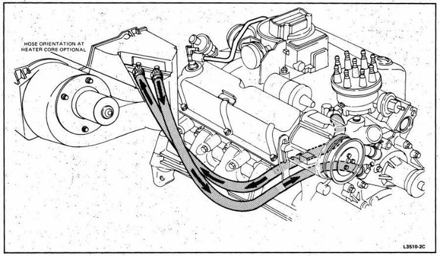
Factory Ford shop manuals are available from Helm Publications, 1-800-782-4356 5) Coolant Flow Diagram: If a heater circuit is not used then the heater supply must be connected to the heater return to allow air to be purged from the right hand cylinder head and provide sufficient coolant flow through the right hand cylinder head. Install a 5/16 ...
Boss 302 engine was fitted with the D0ZZ-8501-B water pump. Ford Water Pump with Left Inlet. Beginning in 1970, water inlet position ...
Realize that the rear heater is an integrated part of the van's cooling system, and don't slice the coolant lines all willy-nilly! Realize that the same is true of the rear A/C, and that the A/C refrigerant lines run right next to the heater coolant lines.
Ford Performance Parts M-9424-F302 - Ford Performance Parts 289/302 Dual Plane Performance Intake Manifolds Intake Manifold, Aluminum, Dual Plane, Square Bore Flange, Ford, 289, 302, Each Part Number: FMS-M-9424-F302
15 Sept 2021 ... So should I over drive my pulley or underdrive my pulley with a hi flow FlowKooler waterpump? Continue reading · Deciphering small block Ford ...
1965-1972 (6 Cyl. 240, 300 and 8 Cyl. 302, 352, 360, 390 engines) - F100/350 1406 x 1024, 383K Valve Assy. - (Exhaust Thermostat Control with Arm Type Counter Weight - Typical
302 overheating. Jump to Latest Follow ... The water pump, radiator and thermostat are brand spankin' new and coolant is not leaking from anywhere. There does not appear to be any air in the system although there is the occasional bubble in the overflow tank. ... Ford Forum is a community to discuss all things Ford. Check out our discussions on ...
The ports flow better due to their round shape and straight path. This design was first used on the 427, and then in 1968 on a special 302. These round intake ports were 3.8 sq. in. in area at the intake manifold face. The Tunnel Port 302 cylinder heads feature 2.12" intake and 1.54" exhaust valves.
Engine Coolant Temperature Sensor - A fundamental part of regulating air/fuel ratio, ignition timing, and EGR flow. A malfunctioning Mustang coolant temperature sensor can provide false information to your Mustang's computer that could cause anything from erratic idle to catastrophic engine failure on your Mustang Engine!
23.11.2021 · F150 ecoboost coolant leak back of engine
Windsor Lubrication Diagram Windsor Coolant Flow Diagram. Now you know why it's so important to install the head gaskets with the "FRONT" markings to the front, even though one of them will be installed with the "FRONT" marking upside down. Need to make sure the water/coolant passages are kept open at the rear of the block, to ensure the flow ...
Use silicone around all coolant holes and head studs on both sides of gasket. Fill the ... This increases the oil flow to the mains and ... FORD 302 SBF Aluminum Block - Technical Notes Part# 31344175 - 31344285 Material: RMR Cast Aluminum Alloy Bore: 4.00" or 4.125" ...
Ford Truck Diagrams and Schematics. Alternator Voltage Regulator Instrument Panel Starter and Drive Distributor
Does anyone have a diagram for the coolant flow direction on a 1990 5.0 EFI HO ?
The engine antifreeze/coolant usage noted in the chart above applies to all engine types (e.g., gasoline and diesel) available for a particular vehicle. G = Green-colored engine coolant approved to Ford specification ESE-M97B44-A (Motorcraft ® Premium Antifreeze/Coolant)
The water flow on all small block fords is the same. In the water pump through the lower hose. Through the block (with trace amounts going to the head through the holes through the head gasket. At the back of the block the water flows through 2 big holes up into the head Then the water flows forward through the heads.
Visit site. Jul 23, 2004. #2. Originates (pushes) at the water pump, flows through the heater core, back to the intake manifold. Note: at the manifold the heater inlet sits next to the engine outlet. Movement of water through the manifold and into the radiator causes a small vaccuum at the heater return line (it sucks)!


0 Response to "38 ford 302 coolant flow diagram"
Post a Comment