36 foot switch wiring diagram
Beginners are often confused about how one should correctly wire a 3PDT foot-switch for true bypass operation. Most often, this is due to a lack of understanding of how the 3PDT switch operates. Let's fix that. Standard Taiwan 3PDT foot-switch fig.1 Fig.1 shows a bottom view of the 3PDT foot-switch.
Collection of foot switch wiring diagram. A wiring diagram is a streamlined conventional pictorial depiction of an electrical circuit. It shows the parts of the circuit as streamlined forms, and the power and also signal connections between the gadgets.
Let's start with the most basic float switch: a two-wire, single-pole, single-throw float switch.The rising action of the float can either close (i.e., turn on) a "Normally Open" circuit, or it can open (turn off) a "Normally Closed" circuit.Installation scenarios might include a Normally Open float switch turning on a pump to empty a tank (Control Schematic 2), or a Normally Closed ...

Foot switch wiring diagram
With the wires attached to the input jack, it's time to connect them to our footswitch. As you can see from our wiring diagram, the wire coming from the sleeve goes to terminal 6 of our footswitch and the wire coming from the tip of the jack input goes to terminal 9 (directly below 6).
Circuit Diagram. This provides a visual reference for wiring of the components. They aren't true to scale, just meant to be used as reference. Generic micro switches follow a standard pin out with visible markings on the body of the switch. Here's each label markings: (C1) - "common ground". (NO2) - "normally open". (NC3) - "normally closed".
wiring a foot-switch 07-23-2014, 09:42 AM. Hi Y'all I am a carpenter not an electrician, how do I wire my new foot-switch so that my scroll-saw works when I push down on the switch, there does not seem to be an earth contact, should there be? this was from China, so no instructions, no surprises there.
Foot switch wiring diagram.
Before going any further, you have to understand how functions a 3PDT footswitch. The 3PDT stands for "3 poles, double throw". Here is a diagram showing the ...
Foot-switch. This document will not become the contractual ... (Three-Step-Safety Switch). 1. position. 2. position ... Wiring diagram PNP additional board.3 pages
Tattoo Foot Pedal Wiring Diagram - wiring diagram is a simplified gratifying pictorial representation of an electrical circuit. It shows the components of the circuit as simplified shapes, and the capability and signal friends amongst the devices. Tattoo Foot Switch Wiring Diagram Do It Yourself Sugru. A wiring diagram usually gives ...
They tend to be only slightly more expensive, but also last longer. A good way to tell a quality switch or outlet is by the reputation of a back-wire feature. READ Ge Washing Machine Motor Wiring Diagram - Database. 6. Test the voltage. Make sure you test the voltage of wires and circuits before touching them.
G-Series heavy-duty foot switches (see below for wiring diagrams) can include from one to three switches, and up to four independent SPDT circuits. They do not come with cables. The user installs the appropriate cable and strain relief to the switch. G500 models have one switch, G502 models have two switches, and G503 models have three switches.
7. The circuit designations shown in Diagram "C" are at assembly. For 974-S only, the left side interior switch is reverse actuated in the foot switch housing. For example, the normally closed terminal (NC) marking molded into the switch body will provide a normally open circuit when the interior switch is assembled in the foot switch housing. 8.
foot switch wiring diagram specifications To wire the actuator to the foot switch for double action (extention/retraction) make the connections between the foot switch, power source (battery), relay and actuator wires as follows: Connection To Relay Terminal 4 NC
3Ø WIRING DIAGRAMS 1Ø WIRING DIAGRAMS Diagram ER9 M 3~ 1 5 9 3 7 11 Low Speed High Speed U1 V1 W1 W2 U2 V2 TK TK Thermal Overloads TWO SPEED STAR/DELTA MOTOR Switch M 3~ 0-10V 20V 415V AC 4-20mA Outp uts Diagram IC2 M 1~ 240V AC 0-10V Outp ut Diagram IC3 M 1~ 0-10V 4-20mA 240V AC Outp uts These diagrams are current at the time of publication ...
All Foot Switch. Ridge Tool. I bought a forward reverse switch that is for a Rigid pipe threader Also note that the Ridgid wiring diagram calls for a foot switch, which. Wiring Diagram. the switch or plugging in tools that have the switch ON invites accidents. • Remove . The RIDGID Model Power Drive can also be used.Page Wiring Diagram.
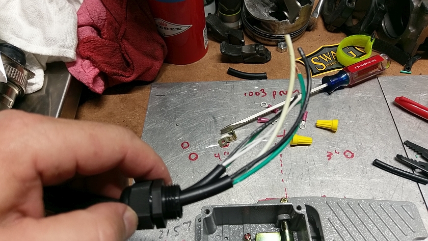
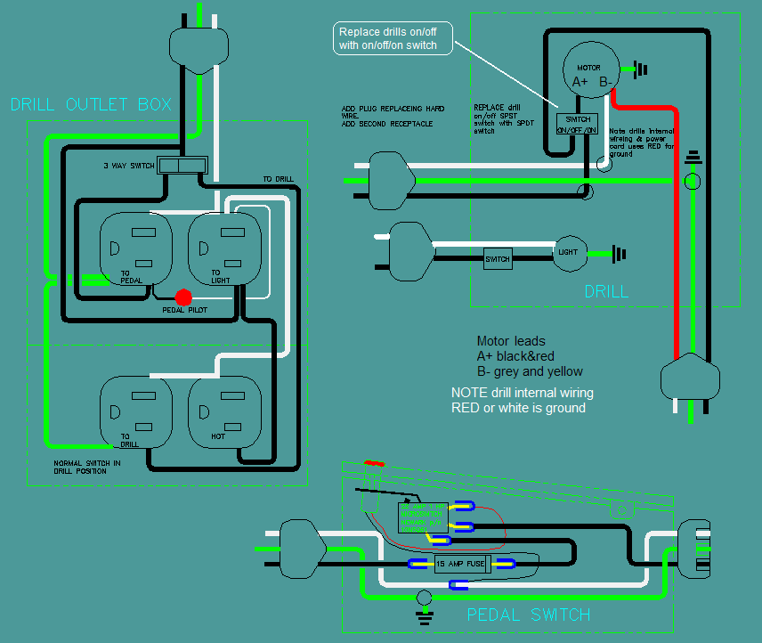
When using some of the power tools, you need to use both hands and also control on/off the tool. In this case, for my drill press I wanted a better control w...
Jan 30, 2018 - Make a simple foot switch controlled cord for your tools. Useful for band saws, and other places where you need both hands.
1. Clipper foot operated switches are furnished with two 7/32 IN. (5.6 mmØ) diameter mounting holes on 2-7/8 IN. (73 mm) centers. 2. Use two number 10 machine screws and two number 10 lock nuts when mounting foot switch to full guard. (See Diagram "C") Form 522-F20 Rev. H #10 Locknut Clipper Foot Switch #522-B14 Full Guard with assembly ...
Ssc controls g500-mo foot switch, heavy duty, made in usa, electrical, momentary action, single pedal, industrial, ul, csa, replaces 531-swh, spdt, 20 ...
see wiring diagram. notes on wiring: 1) the switch is typically wired into one side of the electrical circuit (normally the "hot" side, if applicable). 2) follow all applicable electrical codes and consult an electrician with questions. 3) the white and black lead colors on the foot switch cable have no relevance to household wiring.

Ssc controls g500-mo foot switch, heavy duty, made in usa, electrical, momentary action, single pedal, industrial, ul, csa, replaces 531-swh, spdt, 20 ...
Standard Taiwan 3PDT foot-switch fig Fig.1 shows. That's not always possible (usually is with a wah switch, usually isn't with a 3PDT pedal switch). So then tin the wire and solder the hole in the.3pdt toggle switch wiring diagram datasheet, cross reference, circuit and application notes in pdf format.

Friends, please don't let your freinds sew sheep | sewing ...
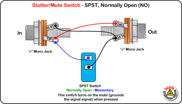
Posted August 14, 2010. Building one without led's is seemple. 2 wire plus shield cable, 2 on/off switches, a box and a trs plug. Shield is ground and goes to the sleeve of the trs plug and to one side of each switch, one wire to each switch and the other end to the left over connectors on the plug.
Beavis audio research
Foot switch wiring diagram specifications to wire the actuator to the foot switch for double action extentionretraction make the connections between the foot switch power source battery relay and actuator wires as follows. In each switch lug 2 is common. Al In Windlass Wiring Diagram With Windlass Wiring Diagram Wiring Wiring Of A Foot Switch
Fixing the wiring on a keyboard sustain pedal - electrical ...
5. Install Terminal Block as Breakout Point. If you get your boat's switch panel fully wired ( more on that here ), then you'll have an easy to install wiring harness coming off pre-installed with heat shrink labels, and ring terminals. This is meant to land on a terminal block like this one.

Diy guitar pedal, guitar pedals, guitar diy
Hey John, I'm looking for some wiring diagrams for my older Motorguide trolling motor. It has the tear drop shaped head and the foot pedal is 5 speed with a 12v/off/24v switch on the side. I'm looking for a wiring diagram that shows how the 12/off/24 switch should be hooked up.

Ssc controls ds100 dual foot switch, electrical, momentary action, two pedal, spdt wired normally open (no), 8-ft cable with leads, no guard, twin ...
Foot Pedal Motorguide Trolling Motor Wiring Diagram Source: i53.photobucket.com READ 55 Chevy Brake Light Wiring Diagram Database Before reading a new schematic, get common and understand all the symbols.

Foot switch with safety kick plate | metal tech controls
Foot Switch Selection Guide. Foot switches can be used to turn electrical equipment on and off with the foot, freeing the hands to perform other operations or providing ergonomic improvement to a workstation. G-Series heavy-duty foot switches (see below for wiring diagrams) can include from 3PDT foot switch wiring, many different ways . Steve ...

Diy guitar amp footswitch & channel changing pedal - diy ...
Foot Switch Wiring Diagram Above is a simple diagram that shows how things get wired. I used an old extension cord and cut a short piece for the socket side. The wiring colors in the USA are BLACK for HOT, WHITE for NEUTRAL and GREEN (or GREEN/YELLOW) for GROUND. As the wiring shows we are really only wiring the BLACK wires to the switch.

Stompboxed - the guitar pedal builders repository: switch ...
Feb 25, · Some digging around revealed that the DigiTech Fs3X pedal would probably work. At this web site I found the following diagram for such a switch. And then on schematron.org I found this pdf that described the FS3X wiring (reproduced here, copyrights acknowledged). Aug 28, · my two button footswitch doesn't work anymore, so i wanna ...

Amz-fx guitar effects blog » blog archive 3pdt switch wiring ...
Heavy Duty Foot Switch CN0003 - Cast Aluminum Foot Switch. SPDT (Single pole, double throw). Wiring Diagram is printed on the nameplate for your convenience. Rated amps: 15A, Rated voltage: 250VAC Cast Aluminum construction Dimensions: 7.91 x 4.00 x 2.95 in (201 x 101.5 x 75 mm) 5 Year Warranty

S-series foot switches for light-duty industrial, home, and shop
Wiring Diagram Book A1 15 B1 B2 16 18 B3 A2 B1 B3 15 Supply voltage 16 18 L M H 2 Levels B2 L1 F U 1 460 V F U 2 L2 L3 GND H1 H3 H2 H4 F U 3 X1A F U 4 F U 5 X2A R Power On Optional X1 X2115 V ... Foot Switches Pressure & Vacuum Switches Liquid Level Switches Temperature Actuated Switches Flow Switches Speed (Plugging) FF R F R Anti-Plug N.O. N.C.

S100-1501 (s-series light-duty foot switch)
What is a Foot Switch? An electrical switch is simply a device that opens or closes an electrical circuit, and a foot switch, sometimes called a "stomp" switch, is operated by someone stepping on the actuator, which is typically a pushbutton or a pedal.. The advantage of using a foot switch is simply that it frees up a person's hands for other work while still allowing a human operator full ...

Foot switch selection guide - ssc controls company

Midi foot pedal controller wiring information

I have a 1/2 hp motor 115/230 volts currently hooked up to a ...

Stompboxed - the guitar pedal builders repository: stompbox ...

Tutorial - wiring a footswitch for a guitar effect do it yourself foot switch

Industrial foot switches
Obscure footswitch question | telecaster guitar forum
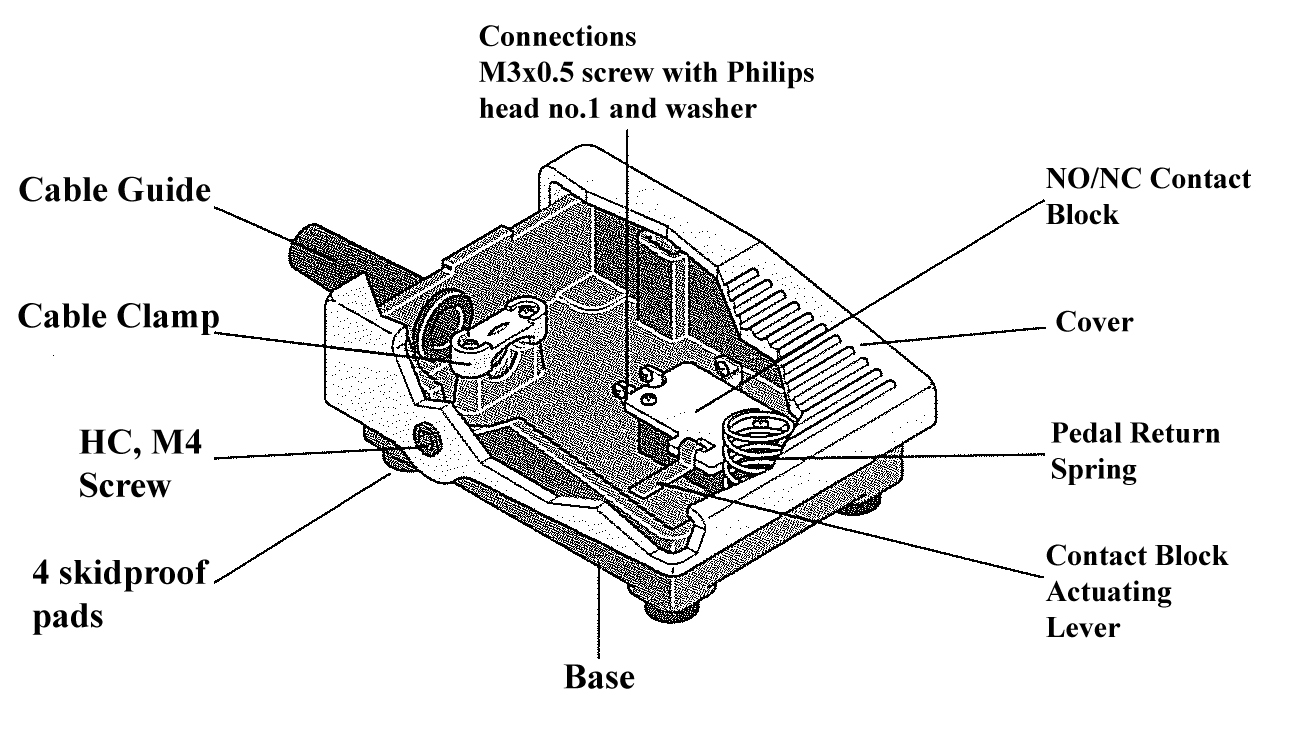
Abb limit switches | choosing an abb limit switch

Diy momentary footswitch pedal for boss or roland gear

Rewiring a duplex receptacle on vintage sewing machines | the ...
Review: pcsensor fs1_p usb foot switch

Vintage singer sewing machines... : singer foot pedal wiring ...
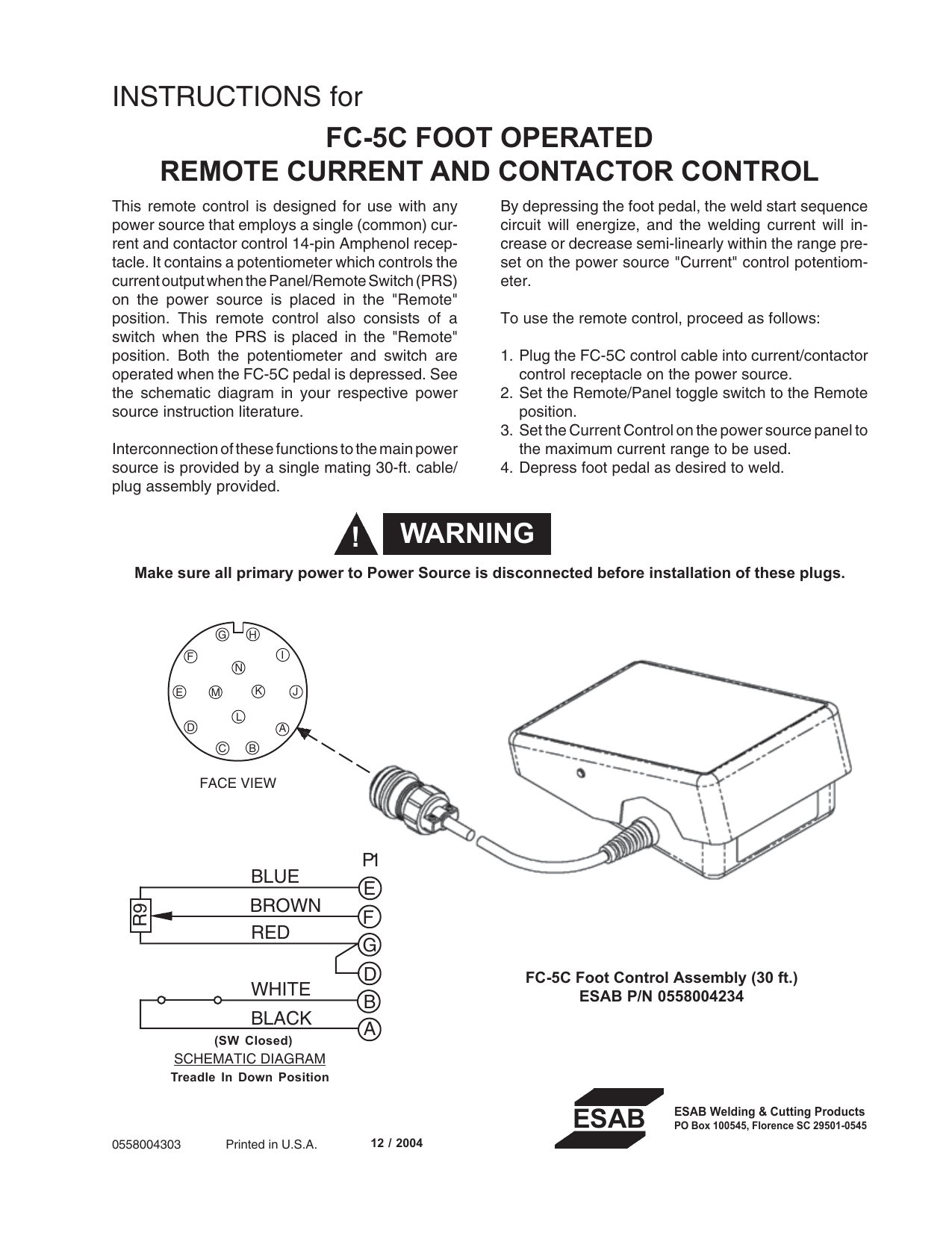
Esab fc-5c foot operated remote current and contactor control ...

Ssc controls b850-1502 foot switch with mounting plate ...

Diy guitar amp footswitch & channel changing pedal - diy ...
Diy foot switch | gtsparkplugs
Weldingweb - welding community for pros and enthusiasts

Buy foot switch,foot control pedal switch,momentary self ...
Machine power pedal switch

Foot pedal - w

A generic stompbox wiring diagram - tonefiend.com | simple ...

Nonslip metal momentary electric power foot pedal switch yblt-ekw/5a/b 12v 24v step siwtch for workshop
0 Response to "36 foot switch wiring diagram"
Post a Comment