35 dish wally installation diagram
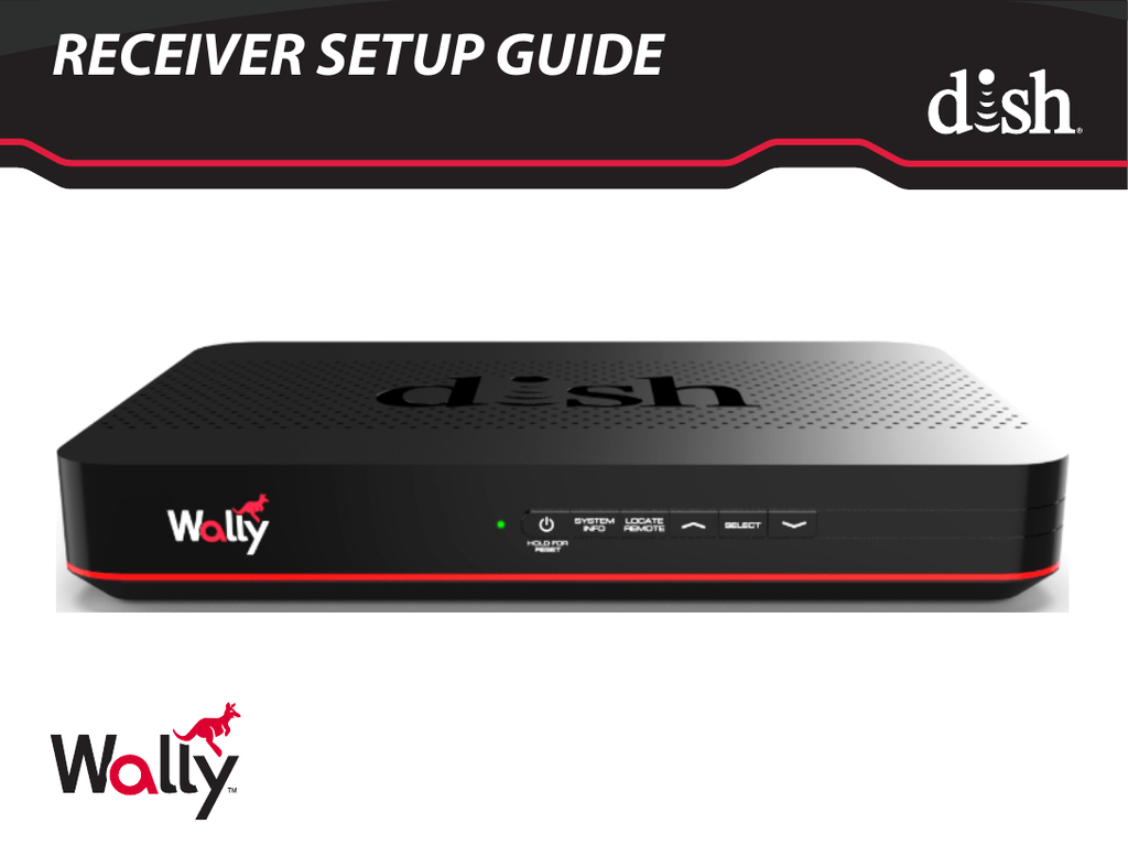
Download the Welcome To DISH manual to see everything your Wally can do. Download the Wally Setup Guide if you need help connecting your new receiver. Reference ...
INSTALLING THE POWER SWITCH DIAGRAM STEPS 2 & 3 TWO GROUND WIRES 1 FROM VEHICLE 1 BLACK WIRE FROM SATELLITE DISH STEPS 4 & 5 RED POWER WIRE FROM DISH STEPS 6 &7 +12 V FROM VEHICLE ON/OFF ROCKER SWITCH WITH LIGHT (Shown in OFF position.) FIGURE 7 10. The GPS antenna is pre-wired and has a 1 meter cable running through one of the connectors.
compatible receiver in the installation to determine connection order from the LNBFs to the DPP44 Switch. Refer to the Wiring Diagrams that begin on "Wiring Diagrams" on page 13. Satellite Locations: For 72.7ºW, 77ºW, 118.7ºW and 121ºW orbits, it is recommended that these orbits be connected to the TO DISH PORT 4 connection. Orbits 61 ...
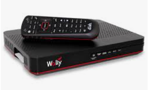
Dish wally installation diagram
Overall Installation 4 InstallationInstallation 5 After installing the TRAV'LER antenna mount base, install a cable entry plate at the location chosen for cables to enter the vehicle from the roof. Drill a 1/2" hole in the roof, and push the power/control cable and one coax cable per receiver through the hole.
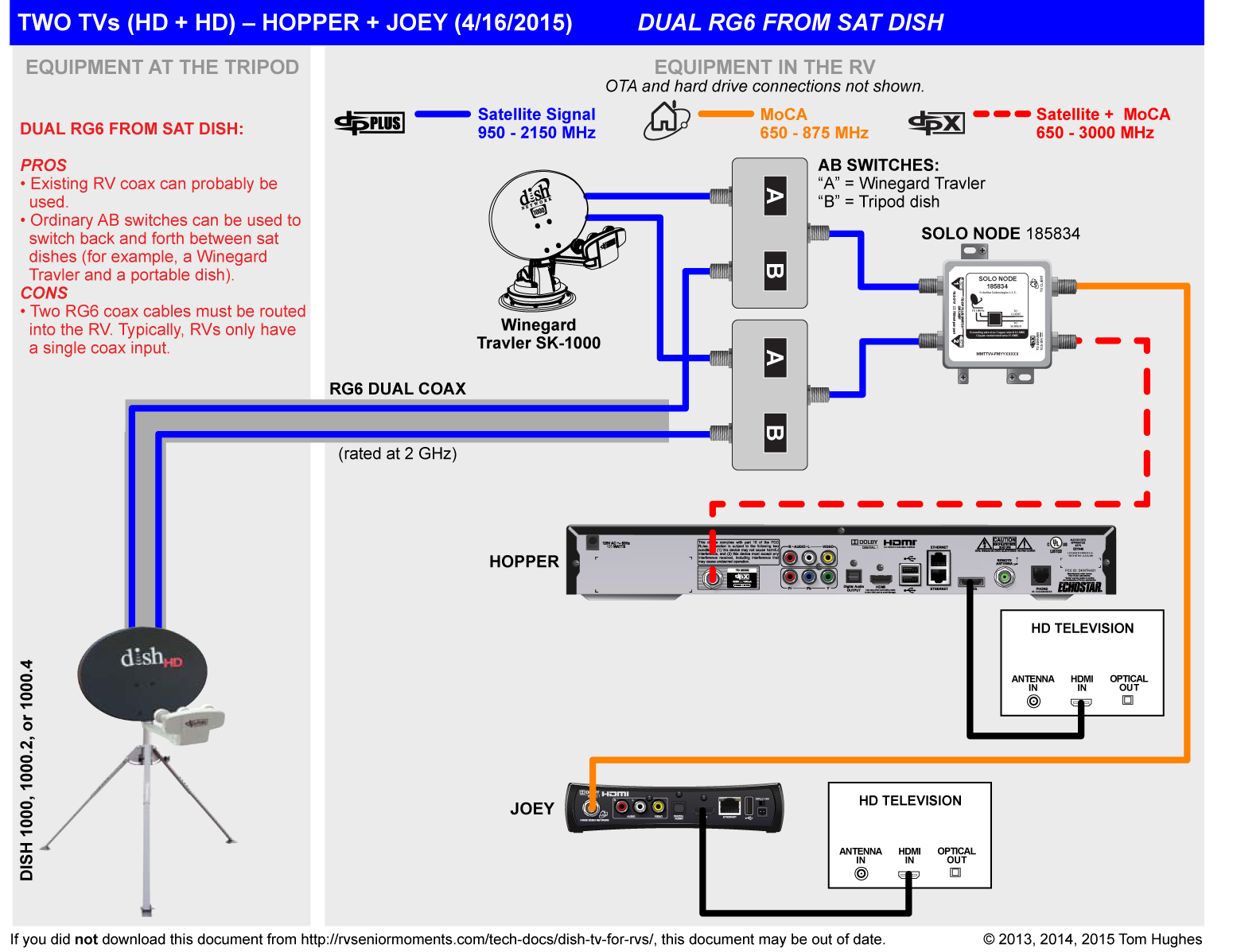
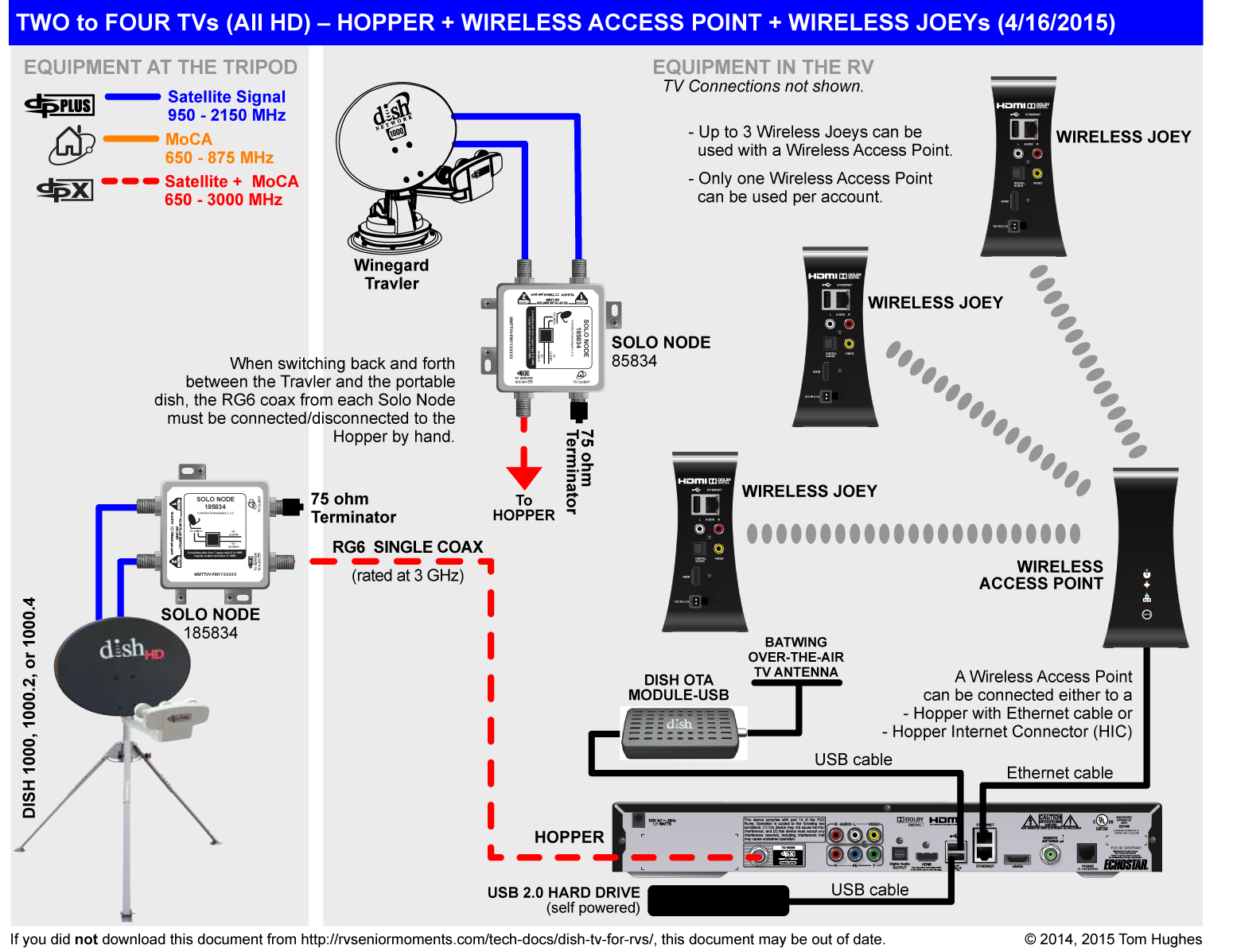
DISH Pro Hybrid To Splitters and then Joeys (As shown on previous wiring diagram). This user guide covers the Wally receiver and may also cover other devices that are . Wired Connection (recommended): Connect an Ethernet cable from the.
A Wait while your Wally acquires satellite signal. This could take up to 10 minutes. Once signal is acquired, the Install Wizard will proceed to the next step automatically. B If red "X's" appear in the installation summary, ensure that the "Home Video Network" cable is firmly connected to your Wally and the wall. Then, use your
Dish wally installation diagram.
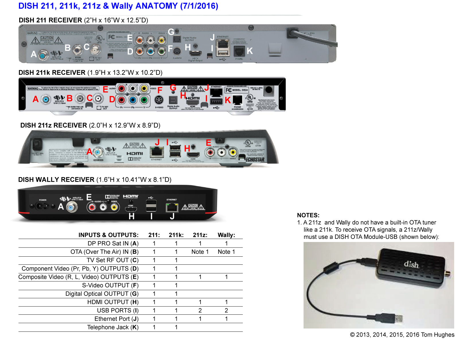
WALLY • The Wally will install the same way the current ViP 211 receivers do ... ViP Receiver Installation Diagrams Here are two of the most common installation configurations for ViP systems. Both examples show a dual ... It is recommended to install the dish antenna and ViP 922 first, then begin the ViP 922 download ...
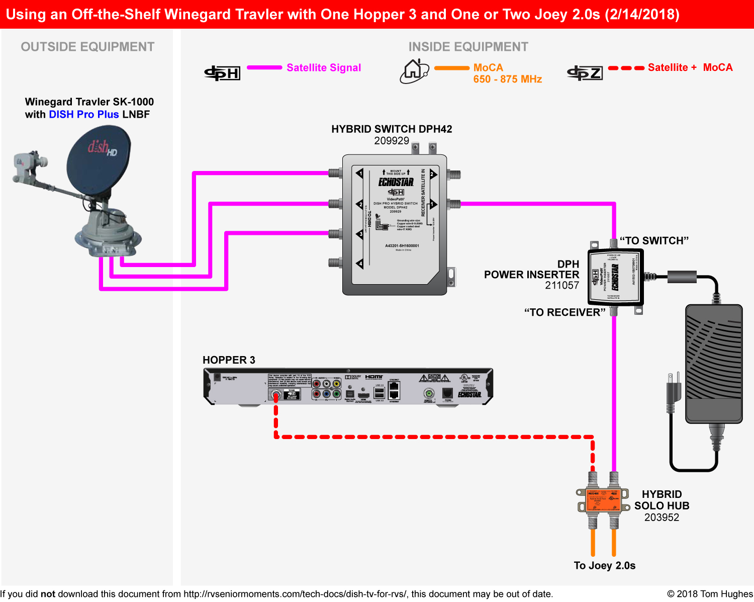
Wiring Diagrams Mixed Receiver System This diagram shows how to connect the DPH42 Switch in an installation that features different supported receivers. Note: For multiple-Wally installations, the DPH42 Power Inserter must be installed between the switch and a splitter, as shown below. Dish Antenna with Dish Pro Plus LNBF RG-6 Coax lines Hopper ...
15,070. Pekin, IL. Apr 21, 2020. #2. There are only 2 outputs on a Hybrid LNBF. Port 1 goes to the Solo Hub or directly to the Hopper, if no Joeys. A Hopper 3 (And a Hopper Duo), when plugged in, "kill" the port 2 output. The Hopper 3 cannot run off of DPP Technology, which is what the 44 switch is.
Dish Wally Installation Diagram - Dish Wally Wiring Diagram Wiring Diagram arrives with several easy to adhere to Wiring Diagram Directions. It is supposed to help all of the typical user in building a correct method. These instructions will be easy to comprehend and apply.
DPH42 Installation Guide 7 3 Ground the system in accordance with the National Electrical Code® (NEC) and all state and local electrical codes. Note: The DPH42 Switch is UL-listed as an approved grounding block. 4 Connect RG-6 cables from the LNBF(s) to the To Dish ports on the DPH42 Switch. Refer to the Wiring Diagrams section on page 8. 5 Connect an RG-6 cable from the switch's ReceiveR ...
3. Turn your DISH Network receiver on. 4. Press the Menu button on your DISH Network remote. 5. Press 6 for System Setup, press 1 for Installation, and then press 1 for Point Dish. 6. On the next screen, click on Check Switch. 7. Check that the Switch says SW64 and check if all three satellites have a green OK in the Trans row. If not, continue ...
There are two things that will be present in any Dish Wally Wiring Diagram. The first element is emblem that indicate electrical component in the circuit. A circuit is usually composed by numerous components. The other thing you will come across a circuit diagram could be traces. Lines in the diagram show how every component connects to a another.
During installation, aiming the satellite dish to get the strongest signal will help prevent rain and snow from interrupting the signal. Semiannual Solar Interference Twice a year, the sun moves to a position behind DISH satellites as they orbit the ... • Use DISH Anywhere to manage your Wally when you're away from home.
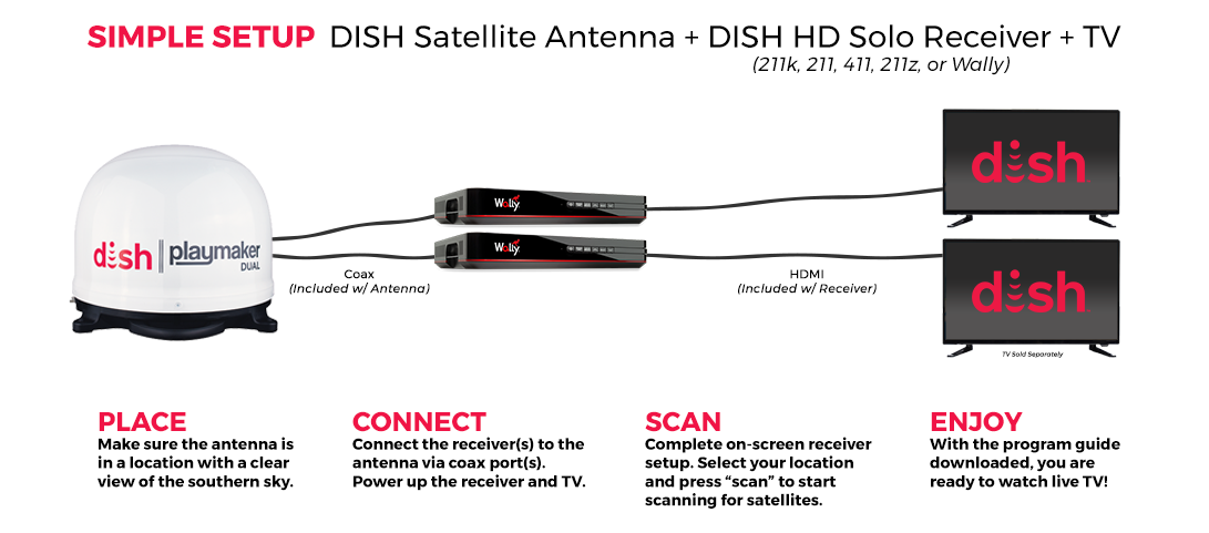
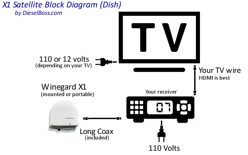
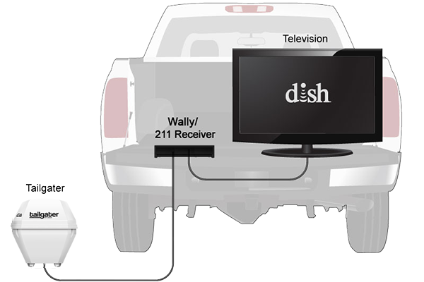
DISH® Wally™ Receiver Setup It is important to follow the directions included with your product for the best possible experience. In order for the DISH Wally receiver to work properly, the mobile antenna must ALWAYS have a clear view of the southern sky.
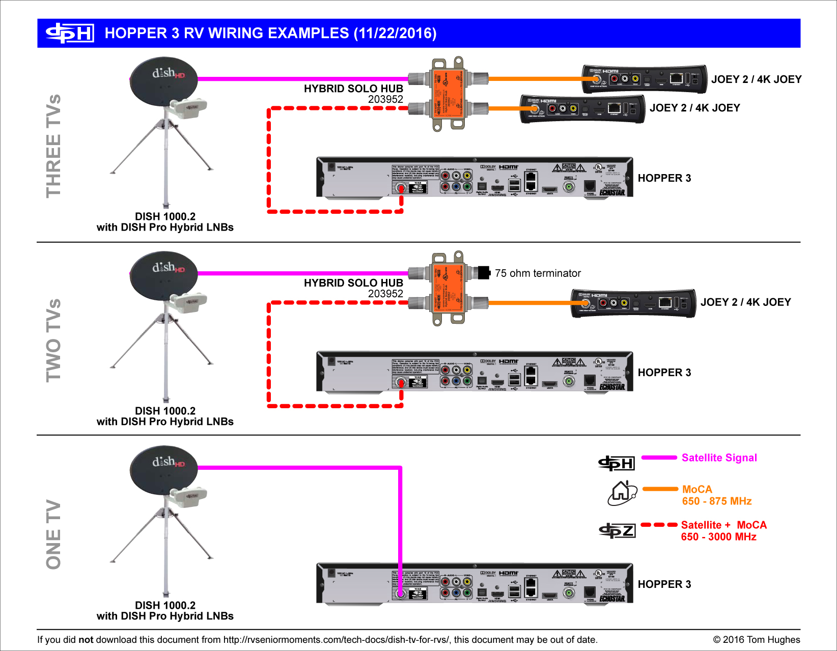
Dish 1000.2 Antenna with Dish Pro Plus LNBF RG-6 Coax lines Hopper 3 DISH Pro Hybrid Solo Hub RG-6 Coax To Splitters and then Joeys (As shown on previous wiring diagram) Max 6 Joey thin-client receivers in same video network as each Hopper 3 (Joeys, 4K Joeys, Wireless Joeys) Hopper 3 RG-6 Coax Amplifier DISH Pro Hybrid 42 Switch RG-6 Coax ...
Dish hopper wiring diagram rf modulator. A wiring diagram is a streamlined standard pictorial representation of an electric circuit. Start date jan 22 2019. Do not install any non-Hopper Joey System components after the Node Taps can only be installed on host lines When using 2 Taps, the entire Hopper Joey System must use RG-6 coaxial cable ...
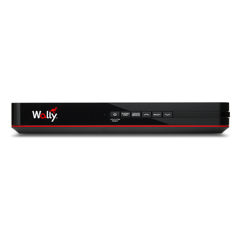
The DISH® Wally HD satellite & WiFi-enabled receiver has a modern look and brand-new user interface capable of supporting a variety of apps like Netflix® & games. It can be customized with accessory products like a Wi-Fi Adapter, Bluetooth Adapter & DVR to create a full entertainment experience in your RV. Or Call 1-800-472-1039.
Dish Wally Installation Diagram 16.12.2018 16.12.2018 3 Comments on Dish Wally Installation Diagram In order for the DISH Wally receiver to work This allows the Wally receiver to pick up Receiver setup instructions are accurate at time of printing and may.
Setup wizard will authorize your Wally. This process will take 10-15 minutes to complete. Once complete, the System Setup wizard will automatically proceed to the next step. c.To begin using your Wally, use the arrows on your remote control to highlight "Watch TV" and then press the SELECT. Please call 1-800-333-DISH (3474) to activate your ...
Dish Network Satellite Wiring Diagram - dish network hd satellite wiring diagram, dish network satellite wiring diagram, Every electrical arrangement consists of various diverse components. Each component should be placed and linked to different parts in particular way. Otherwise, the arrangement won't function as it ought to be.
a. Offers enough support for a secure installation b. Allows dish to raise and rotate without interference from other roof-mounted equipment c. Has a minimum roof space of 42" x 25" for the mounted within a 32.5" radius from the center of the TRAV'LER base location where a gap of 3/16" or more exists between the bottom of the antenna
Hopper Receiver Installation Generated by Jive on 2018-06-25-07:00 6 The contents and Features labels for the Joeys are: Joey 2.0 (note the light blue border) Joey 1.0 Joey 2.0 Installation Diagrams For detailed installation diagrams, visit Receiver Installation Diagrams - Joey. (Note: Joey = Joey 2.0 or Joey 1.0 in that document) Return to Top ...
we need the days where we could plug a receiver into each output on the LNB with no issues.. haha. I am working on that for a friend.. they have the equipment and a dish and just trying to get it hooked up. I have 2 hopper 3's and 3 Joey 3.0 here at my home. Running on a DHP42 switch. Looks like a DPP LNB out on the dish.
a. If you are installing a single cable installation with a DISH Pro Plus Separator to a DISH Pro Plus dual-tuner receiver, install a DISH Pro Plus Separator as follows (see Figure 14 on page 17): 1) Connect a cable from the DISH Pro Plus Twin LNBF output (Port 1 or Port 2) to the DISH Pro Plus Separator Input.
D When the Install Wizard screen appears, go to step 5. ... highlight either the “DISH Account ... STEP 9: Activate Your Wally (Internet Connection Cont.).
View online (16 pages) or download PDF (2 MB) Dish Network WALLY User manual • WALLY PDF manual ... HDMI cable or RCA cables as your audio/video connection.
Wiring Diagrams Mixed Receiver System This diagram shows how to connect the DPH42 Switch in an installation that features different supported receivers. Note: For multiple-Wally installations, the DPH42 Power Inserter must be installed between the switch and a splitter, as shown below. Dish Network Wally Setup Manual. Hide thumbs.
View and Download Dish Network Wally setup manual online. Wally receiver pdf manual download.
DISH Pro Hybrid To Splitters and then Joeys (As shown on previous wiring diagram). This user guide covers the Wally receiver and may also cover other ...
Wally ® Receiver If using a new Wally receiver with the DISH ® Playmaker ® / DISH ® Playmaker ® Dual antenna, the receiver will go through an Installation Wizard to help with the setup process. Follow the on-screen instructions to program the remote control. Step 1 of the Installation Wizard will pair the remote to the receiver.
In order for the DISH Wally receiver to work properly, the mobile antenna must ALWAYS have a clear view of the southern sky. This allows the Wally receiver to ...3 pages
To set the antenna for DISH or Bell, locate the switches on the Power Inserter and set according to the diagram at the right. Installing the Handle 1) Locate the handle in the box. With "WINEGARD" on the handle facing upwards, align the handle in the base. 2) Thread the two provided screws from hardware bag through the two aligned
Dish is not allowing customers to have mixed equipment. Dish network hopper 3 wiring diagram.Use only the equipment that is listed on the work order for a hopper 3 installation hopper 3 can only be installed with dish pro hybrid dph equipment hopper 3 must be connected to port 1 on the dph lnbf hopper 3 requires 3ghz cable to be used for the host line joey 2 0 4k joey and wireless joeys can be ...
How To A Dvd Recorder Directv Or Dish Network Satellite. Dish network installation steps dss dbs single satellite dual lnb prewiring your home for dvd vcr tv rf modulator converting a winegard trav ler antenna hopper whole hd dvr how do i connect the cable to audio consumer guide welcome adobe golive 5 receiver truck drivers wiring diagrams dishes portable pointing angle mydish electrical ...
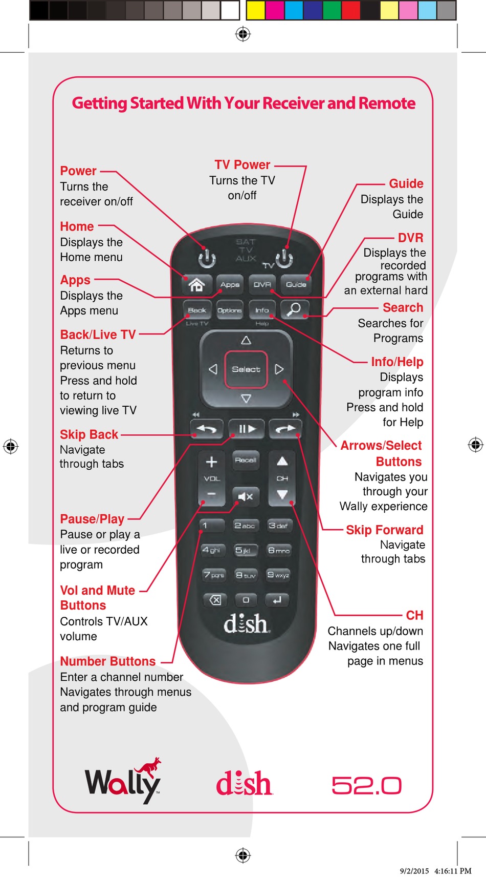










0 Response to "35 dish wally installation diagram"
Post a Comment