41 in a state transition diagram, the circle to the left is the final state.
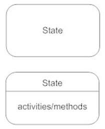
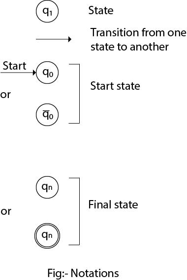
A state is denoted by a round-cornered rectangle with the name of the state written inside it. Initial and Final States. The initial state is denoted by a filled black circle and may be labeled with a name. The final state is denoted by a circle with a dot inside and may also be labeled with a name. Transitions Such a graph is called a state transition diagram. • One state is initial (denoted by a short incoming arrow), and several are final/accepting (denoted by a double circle). For every symbol a a emanating from every state. • • Automata are string processing devices. The arc from q 1
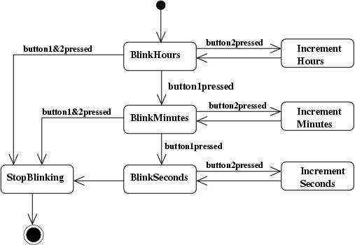
Each state diagram typically begins with a dark circle that indicates the initial state and ends with a bordered circle that denotes the final state. However, despite having clear start and end points, state diagrams are not necessarily the best tool for capturing an overall progression of events. Rather, they illustrate specific kinds of ...
In a state transition diagram, the circle to the left is the final state.
In a state transition diagram, the circle to the left is the final state. diagram A use case ____ is a visual summary of several related use cases within a system or subsystem. A transition diagram or state transition diagram is a directed graph which can be constructed as follows: There is a node for each state in Q, which is represented by the circle. There is a directed edge from node q to node p labeled a if δ(q, a) = p. In the start state, there is an arrow with no source. Accepting states or final states are ... The state diagram in Fig 1 shows a FSM with input alphabet 0,1 and output alphabet ... denoted by a double circle. In Fig 1, states B and D are accepting, A and C are nonÑaccepting. The numbers on the edges are the inputs. ... Make the output 1 for each transition into an accepting state and 0 for each transition in a nonÑaccepting state. Fig ...
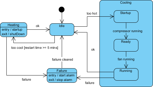
In a state transition diagram, the circle to the left is the final state.. How to draw a state diagram. Each diagram usually begins with a dark circle that represents the initial state and ends with a bordered circle that represents the final state. States are denoted with rectangles with rounded corners. Each rectangle is labeled with the name of the state. And transitions are marked with arrows that link one state ... A UML state diagram also referred to as a state machine, holds information of an object with regards to the state the object is in and the transitions in between. By visualizing an object's behavior and its possible transitive states, a state diagram, also a statechart diagram gives you a better understanding of an object's behavior. A state diagram is used to represent the condition of the system or part of the system at finite instances of time. It's a behavioral diagram and it represents the behavior using finite state transitions. State diagrams are also referred to as State machines and State-chart Diagrams.These terms are often used interchangeably. So simply, a state diagram is used to model the dynamic behavior ... View full document. See Page 1. Question 17 4 out of 4 points In a state transition diagram, the circle to the left is the final state. Answer. Selected Answer: False Correct Answer: False Question 18 4 out of 4 points If you do not use a CASE-generated model, it is not necessary that a diagram or object definition be supported by documentation.
A statechart diagram shows a state ... A final state is represented as a filled black circle surrounded by an unfilled circle. Initial and final states are really pseudostates. Neither may have the usual parts of a normal state, except for a name. A transition from an initial state to a final state may have the full complement of features ... An input alphabet Σ not containing ε. A transition functionset of next states (or successor states). An element s 0 of S, the start state. A subset F of S, the accepting states (or final states). An NFA is basically a flow chart like the transition diagrams we have already seen. Indeed an NFA (or a DFA, to be formally defined soon) can be ... Click on "Shapes" in the upper-left corner of your window and check "UML.". The UML shape libraries will then appear on the left side of your window. Scroll down for the state diagram library and drag out a black circle to start the diagram. This circle indicates the initial state. Diagramming is quick and easy with Lucidchart. Initial and Final States. The initial state of a state machine diagram, known as an initial pseudo-state, is indicated with a solid circle. A transition from this state will show the first real state The final state of a state machine diagram is shown as concentric circles. An open loop state machine represents an object that may terminate before the system terminates, while a closed loop ...
A transition diagram for a DFA M= (Q,∑,δ, q0, F) is a graph defined as follows: 1. For each state in Q there is a node. 2. For each state q in Q and each input symbol a in ∑, Let δ(q,a) =p then the transition diagram has an arc from node q to node p, labeled a. If there are several input symbols that cause transitions from q to p, then ... State-Transition diagrams are not applicable when the system has no state or does not need to respond to real-time events from outside of the system. An example is a payroll program that reads an employee's time record, computes pay, subtracts deductions, saves the record, prints a paycheck, and repeats the process. In a state transition diagram, the circle to the left is the final state.ANS: F. PTS: 1 REF: 24123. A class diagram resembles a horizontal flowchart that ... In a state transition diagram, the circle at the right with a hollow border is the initial state. False.
Initial and Final States. The initial state of a state machine diagram, known as an initial pseudo-state, is indicated with a solid circle. A transition from this state will show the first real state; The final state of a state machine diagram is shown as concentric circles. An open-loop state machine represents an object that may terminate ...
The diagram for hydrogen is shown above. The n = 1 state is known as the ground state, while higher n states are known as excited states. If the electron in the atom makes a transition from a particular state to a lower state, it is losing energy.
Transcribed image text: The figure below shows the state transition diagram of a finite state machine (FSM). This diagram shows the input conditions which initiate the transition. If no input condition is satisfied, then the FSM remains in the same state. a 1 start st task1 tl FSM termin task2 clock The outputs are defined in the following Table: state start st taskl ask2 ermin ul Implement ...
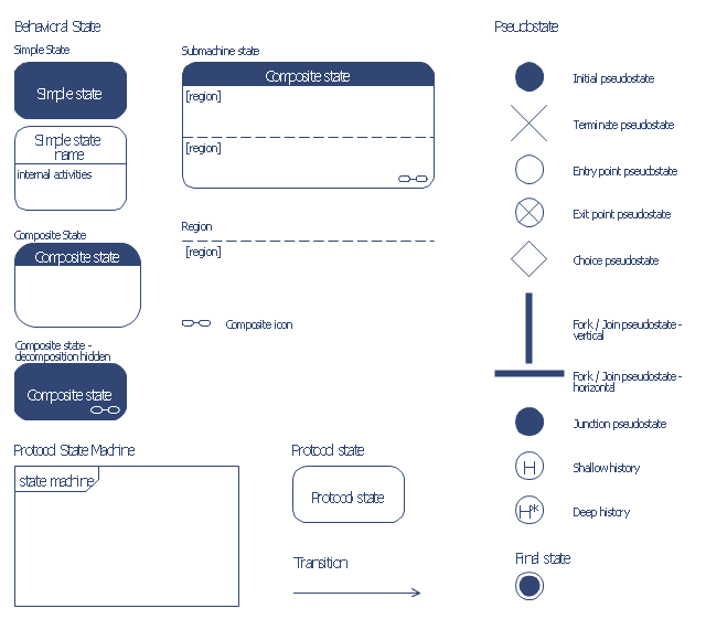
State Machine Diagrams. State machine diagram is a behavior diagram which shows discrete behavior of a part of designed system through finite state transitions. State machine diagrams can also be used to express the usage protocol of part of a system. Two kinds of state machines defined in UML 2.4 are . behavioral state machine, and; protocol state machine
In a state transition diagram, the states appear as rounded rectangles with the state names inside. T 22. In a state transition diagram, the circle to the left is the final state. F 23. A class diagram resembles a horizontal flowchart that shows the actions and events as they occur. F 24.
Each state diagram must include at least one initial state and one final state (double circle). All sequences must begin with an initial state and continue until they terminate with a final state. The set of states included in a state diagram can be thought of as a one-dimensional attribute space where the single attribute has values, which ...
State Transition Testing is a black box testing technique in which changes made in input conditions cause state changes or output changes in the Application under Test(AUT). State transition testing helps to analyze behaviour of an application for different input conditions. Testers can provide positive and negative input test values and record the system behavior.
Tutorial - 5 Steps to Draw a State Machine Diagram Page 5 of 11 7. Release the mouse button. In the popup pane, select Transit -> Final State. This creates a final state. 8. Click a self-transition on the state account with funds. Move your mouse pointer over the state account with funds and click on the Resource Catalog button. 9.

Home sweet home - J.S. Gordon (John Sloan Gordon) O.S.A., R.C.A.- (1886 - 1940) - 1904 - 1907 oil painting on canvas of a Lone rider
In a state transition diagram, the circle to the left is the final state. False When planning an information system, a company must consider how a new system will interface with older systems, which are called ____.
State Diagram Approach The state of a rate 1/2 encoder is defined by the most (K-1) message bits moved into the encoder as illustrated in the diagram below. The corresponding state diagram for the rate 1/2, K = 3 convolutional code is shown below. Notice that there are four states [00] , [01], [10], [11], corresponding to the (K-1)=2 binary ...
In a state transition diagram, the circle at the right with a hollow border is the initial state. True/False. Answer: False. In a state transition diagram, the circle to the left is the final state. True/False. Answer: False. Topic Covered. State Transition Diagram with example in software engineering.
A state represents a stage in the behavior pattern of an object, and like UML activity diagrams it is possible to have initial states and final states. An initial state, also called a creation state, is the one that an object is in when it is first created, whereas a final state is one in which no transitions lead out of.
In a state transition diagram, the circle at the right with a hollow border is the initial state. False. In a state transition diagram, the circle to the left is the final state. False. In a state transition diagram, the states appear as rounded rectangles with the state names inside.
The state diagram in Fig 1 shows a FSM with input alphabet 0,1 and output alphabet ... denoted by a double circle. In Fig 1, states B and D are accepting, A and C are nonÑaccepting. The numbers on the edges are the inputs. ... Make the output 1 for each transition into an accepting state and 0 for each transition in a nonÑaccepting state. Fig ...
A transition diagram or state transition diagram is a directed graph which can be constructed as follows: There is a node for each state in Q, which is represented by the circle. There is a directed edge from node q to node p labeled a if δ(q, a) = p. In the start state, there is an arrow with no source. Accepting states or final states are ...
In a state transition diagram, the circle to the left is the final state. diagram A use case ____ is a visual summary of several related use cases within a system or subsystem.







0 Response to "41 in a state transition diagram, the circle to the left is the final state."
Post a Comment