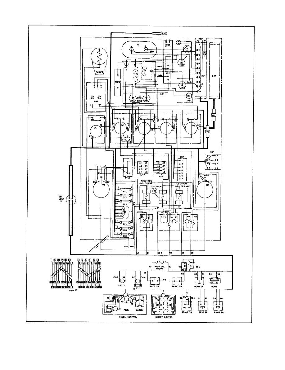
40 pump control panel wiring diagram schematic
Basics 7 4.16 kV 3-Line Diagram : Basics 8 AOV Elementary & Block Diagram : Basics 9 4.16 kV Pump Schematic : Basics 10 480 V Pump Schematic : Basics 11 MOV Schematic (with Block included) Basics 12 12-/208 VAC Panel Diagram : Basics 13 Valve Limit Switch Legend : Basics 14 AOV Schematic (with Block included) Basics 15 Wiring (or Connection ... Wiring diagrams for all control and electrical panels. Diagrams shall (e) Electrical schematic diagram of the pump station as supplied, prepared in. Economy Duplex Sump Pump Control The duplex control provides alternating operation of two volt pumps. Plug-in ready wiring makes installation easy! Simply plug the pumps into the provided receptacles.
pump control panel wiring diagram schematic free wiring diagram Electrical Wiring ... New Fire Alarm Pull Station Wiring Diagram | Wiring Diagram Image.

Pump control panel wiring diagram schematic
Submersible pump wiring diagram control panel pumping station pumps electronics electrical wires cable engineering png pngwing aim manual page 54 single phase motors and controls motor maintenance north america water franklin electric microcontroller three power 1000x648px circuit breaker magnum controller compact is a powerful controlling device for your made with hea two alternately homemade ... Flygt Pump Control Panel Wiring Diagram. Square 1 design manufacture inc submersible pump wiring diagram control how to install and wire a well float switch installation minicas panels xylem canada flygt bs 2750 us diagrams. Submersible Pump Wiring Diagram Control Panel Pumping Station Png 1000x648px Circuit Component. Pump Control Panel Wiring Diagram Schematic Sample. pump control panel wiring diagram schematic - Just What's Wiring Diagram? A wiring diagram is a kind of schematic which makes use of abstract photographic signs to show all the interconnections of components in a system. Electrical wiring diagrams are comprised of 2 things: signs that stand for the parts…
Pump control panel wiring diagram schematic. Control voltage is 120 VAC · Use IEC devices · 22mm pilot devices · Wallmount enclosure – outdoor rated · Main circuit breaker with door mounted operating handle ... Assortment of pump control panel wiring diagram schematic. A wiring diagram is a simplified traditional photographic depiction of an electric circuit. It shows ... page 26 — st4/st6 series submersible pumps • operation anD parts manual — rev. #1 (11/12/13). CONTROL BOX WIRING DIAGRAM (CB1269/CB1274).2 pages Assortment of duplex pump control panel wiring diagram. A wiring diagram is a simplified traditional pictorial representation of an electric circuit. It reveals the components of the circuit as streamlined shapes, and also the power as well as signal links in between the gadgets.
PUMP STATION. CONTROL PANELS. Page 2. ENCLOSURES. ○ RATINGS. ○ MATERIALS OF ... Disconnects. Fusible or Circuit Breaker. Page 7. Generator Provisions.31 pages Wiring Diagram Electrical Wires Cable Schematic Sump Pump Png 1080x897px Area Harness. Sump pump control panel wiring diagram how to create a circuit fill controller float switch installation switches pilot devices solid state submersible single phase simplex automatic water full 3 bat waterproofing ups for back up electrical wires cable tank level madison company install and wire well alarm ... Line diagrams, also called “schematic” or “elementary” diagrams, show the circuits which form the basic operation of the controller. They do not indicate the ... Duplex Pump Control Panel Wiring Diagram Schematic. Duplex 115 208 230v 1 phase control panel three alternating pump m sprecher schuh custom lift station demand wd3p 4 booster controllers overview eaton sewage model 322 sje rhombus. Duplex Demand Control Panel 115 230v Single Phase Individual Pump Circuit Breakers Definite Purpose Contactor.
Fire Pump Controller Wiring Diagram Download. fire pump controller wiring diagram - Exactly What's Wiring Diagram? A wiring diagram is a type of schematic which makes use of abstract pictorial signs to show all the affiliations of parts in a system. Electrical wiring layouts are made up of 2 points: symbols that represent the components in… Pump Control Panel Wiring Diagram Schematic – wiring diagram is a simplified conventional pictorial representation of an electrical circuit. It shows the components of the circuit as simplified shapes, and the capability and signal associates amid the devices. A wiring diagram usually gives guidance roughly the relative face and concord of ... Pump Control Panel Wiring Diagram Schematic Sample. pump control panel wiring diagram schematic - Just What's Wiring Diagram? A wiring diagram is a kind of schematic which makes use of abstract photographic signs to show all the interconnections of components in a system. Electrical wiring diagrams are comprised of 2 things: signs that stand for the parts… Flygt Pump Control Panel Wiring Diagram. Square 1 design manufacture inc submersible pump wiring diagram control how to install and wire a well float switch installation minicas panels xylem canada flygt bs 2750 us diagrams. Submersible Pump Wiring Diagram Control Panel Pumping Station Png 1000x648px Circuit Component.
Submersible pump wiring diagram control panel pumping station pumps electronics electrical wires cable engineering png pngwing aim manual page 54 single phase motors and controls motor maintenance north america water franklin electric microcontroller three power 1000x648px circuit breaker magnum controller compact is a powerful controlling device for your made with hea two alternately homemade ...


0 Response to "40 pump control panel wiring diagram schematic"
Post a Comment