40 free body diagram for pulley
For pulleys above 3-12 in. The included angle for the V-belt is usually from 30 to 40. A A Two Pulley Belt Drive B Free Body Diagrams Of The Belt On The Download Scientific Diagram The V-belts are made of fabric and cords moulded in rubber and covered with fabric and rubber. As an illustration of how a pulley works, consider the diagram at the right. ... The free-body diagrams for each individual mass are shown below.
13:20Complex Pulley With 2 Angles Sample Problem Using Free Body Diagrams. Watch later. Share. Copy link ...Jan 24, 2016 · Uploaded by Physicshelp Canada
Free body diagram for pulley
Remember that a free-body diagram must only include the external forces acting on the body of ... A light rope is attached to it and runs over a pulley.Net external force: →Fnet=∑→F=→F1+→F2+...Definition of weight, vector form: →w=m→gw...Newton’s second law, vector form: →Fnet=∑...Newton’s second law, component form: ∑→Fx... Powerful Pulleys. Students learn how a pulley can be used to change the direction of applied forces and move/lift extremely heavy objects, and the powerful mechanical advantages of using a multiple-pulley system. ... free body diagram: A stripped-down diagram in which only one body is considered. That body is represented by a sketch or simply a ... Free body force diagram with 3 pulleys [closed] Ask Question Asked 8 months ago. Active 8 months ago. Viewed 31 times 1 1 $\begingroup$ Homework-like questions and check-my-work questions are considered off-topic here, particularly when asking about specific computations instead of underlying physics concepts. Homework questions can be on-topic ...
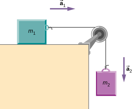
Free body diagram for pulley. I attached an image of the free body diagrams I drew of crate #1 and #2. Using these diagram, we can set up a system of equations for the sum of forces in the x and y direction. ∑Fₓ = maₓ ∑Fᵧ = maᵧ . Let's start with the free body diagram for crate #2. Let's set the positive direction on top and the negative direction on the bottom. 4. Now apply 'F =ma' to the pulley (remembering the pulley has negligible mass). 5. You should now have an equation relating the tensions. If you don't, post your working for each of the above steps. 1. I've uploaded a free body diagram of the pulley near M 1. 2. Forces directly acting on the pulley are the two T 1 acting down the slope and the ... For the system shown at right, identify the correct free body diagram for the frictionless pulley ... A landing gear mechanism is shown in the accompanying figure.. exerts two forces on the end of the landing gear as shown. Determine the horizontal and vertical components of reaction at the pin C and the force in strut AB. 20.. 3:51This video solves for the acceleration of a person who is connected to a pulley. This involves drawing a free ...Aug 21, 2016 · Uploaded by The Ryder Project
The free body diagram is a diagram of the forces in the system without the physical body details, in the attached we have a free body diagram. Let's write the equation for each axis y-axis N - = 0 N = x-axis Wₓ -fr -T = m a Let's use trigonometric to break down the weight cos 37 = sin 37 = From the free-body diagram of the 0.3 kg block, T = 0.3g ⇒ T= 0.3 × 10 = 3 N Now, from the free-body diagram of the 0.2 kg block, T 1 = 0.2g + T ⇒ T 1 = 0.2 × 10 + 3 = 5 N ∴ The tensions in the two strings are 5 N and 3 N, respectively. Question-5. Two blocks of equal mass m are tied to each other through a light string. Free Body Diagram. FBD is a tool used to solve statistical problems. FBD is a pictorial representation of a body or element, when all other connecting elements are removed. It helps to simplify the analysis of practical problems. Moment of Forces. Moment of force is basically force multiplied by distance about which we calculate moment of inertia. Provide a free body diagram and all necessary bending moments and torque diagrams. Calculate the dimensions of the keys and the key ways at shaft 1 and 2 for the two gears and the pulleys. November 1, 2021 / in Technology / by Sam. Shaft Design.
Pulley A, pulley B and pulley C are fixed at positions 20°, 340° and 180° respectively on the vector force table. ... Resultant Force on an Object in Various States of Motion A free body diagram of an object is a diagram that shows all the forces acting on that object only. Figure 1.3 shows the free body diagram of a book on a table. The free-body diagram for each individual mass is shown below. Each object is experiencing a downward force of gravity (F grav ) - calculated as m 1 •g and m 2 •g respectively. The glider (m 1 ) is experiencing an upward support force (air pushing up on it) to balance the force of gravity. 1:52Pulleys and Tension ProblemSum of Forces in Inclined Frames of ReferencePulleys, Tension, and Extension ...Jan 19, 2021 · Uploaded by Less Boring Lectures smooth pulley of radius 20 cm. The moment of inertia of the pulley is 2 kg m2. (i) Sketch the free body diagram of the 1.5 kg block. (ii) When the mass is released from rest, calculate the angular velocity and number of revolutions of the pulley at t = 4.2 s.
Free body diagrams [edit] The mechanical advantage of a pulley system can be analysed using free body diagrams which balance the tension force in the rope with the force of gravity on the load. In an ideal system, the massless and frictionless pulleys do not dissipate energy and allow for a change of direction of a rope that does not stretch or ...
4.3.2 Draw a free-body diagram showing ALL forces acting on the box while moving from B to C. (3) 4.3.3 Use the energy principles to calculate the kinetic frictional force between B and C if the speed of the box at position C, the bottom of the plane is 3 m•s-1. (5) 4.4 The angle between the incline and the horizontal is decreased.
Pulley problems for IIT JEE and JEE Main - Excellent way to practice free body diagrams and master application of newtons second law of motion.
Provide a free body diagram and all necessary bending moments and torque diagrams. 2. Calculate the dimensions of the keys and the keyways at shaft 1 and 2 for the two gears and the pulleys. 3. Determine the critical speed of rotating shaf t 2. B. DRAWINGS AND ASSEMBLY 1. Make the construction drawings of all different parts (2D) 2.
Free Body Diagram Pulley With Mass. Written By JupiterZ Wednesday, April 17, 2019 Add Comment Edit. 3 venn diagram transparent transparent 3 circle venn diagram transparent 3 way venn diagram. 3 Venn Diagram Transparent. Written By JupiterZ April 17, 2019 Add Comment Edit.
In this post, we will learn how to draw the free body diagram of Atwood's Machine in LaTeX using TikZ package. At the end of this tutorial, we will be able to: 1) draw a circle, a rectangle and a trapezium; 2) fill a shape with patterns and create smooth corners. 3) draw arrows and add labels.
Also, let the magnitude of accelerations be “a”. Static pulley system. Free body diagram of body of mass 10 kg.
A free body diagram consists of a allegorical representation of a distinct body or a subsystem of bodies abandoned from its ambience assuming all the armament acting on it. In physics and engineering, a free body diagram (force diagram, or FBD)..This physics video tutorial explains how to draw free body diagrams for altered situations accurate those that absorb connected acceleration and constant.
Simple machines make use of mechanical means to apply force and perform work. Learn about different types of simple machines such as the lever, inclined plane, and pulley, and determine the ...
Free Body Diagrams are used to solve problems in Mechanics. The sketch of an object with all the surrounding objects stripped away and all of the forces acting on the body is shown is called a free body diagram. It helps to solve and analyses the questions involving the forces.
Answer: Aha, your pulley image has appeared! Just 1 support strand (although 2 pulleys) and 1 effort strand as usual. The VR = 1 and if the pulleys are weightless, the Effort is the same as the Load Earlier answer I'm reluctant to scrap. That depends very much on how many pulleys and how they ...
9:50Making accurate free body diagrams for a system of blocks connected by string and pulleys is an important ...Aug 20, 2017 · Uploaded by The Science Cube
33 Free Body Diagram Inclined. You will be presented with a verbal description of a physical situation for which you must construct a free body diagram. You need to first understand all the forces acting on the object and then represent these force by arrows in the direction of the force to be drawn.
Free Body Diagram of Suspended Man The man is sliding across the rope on a bar and being pulled by the tension T. Ignore any frictional effects.
5:54Visit http://ilectureonline.com for more math and science lectures!In this video I will show the “traditional” and the ...Oct 13, 2017 · Uploaded by Michel van Biezen
For T₂, its free-body diagram shows us it is only responsible for the mass of m₂, we can say that T₂ = a * m₂. With that said, T₂ = (2.4 m/s²) * (2 kg) = 4.8 N . On the other hand, T₁ is the tension force that pulls both the weight of m₁ and m₂.
Draw the free body diagram to see the internal forces and use equilibrium equation in vertical direction and balance the pulley using the block weights. Take care of the units and sign conventions. While drawing the free body diagram make sure the direction of forces should be as per given in the question.
smooth pulley of radius 20 cm. The moment of inertia of the pulley is 2 kg m2. (i) Sketch the free body diagram of the 1.5 kg block. (ii) When the mass is released from rest, calculate the angular velocity and number of . revolutions of the pulley at t = 4.2 s.
A free-body diagram is a pictorial representation in which the body under study is assumed free from the rest of the system i.e. assumed separated from the rest of the interacting bodies and is drawn in its actual shape and orientation and all the forces acting on the body are shown.
If I just assumed that this is how the string applies tension on the pulley, I was able to solve the problem, but I fail to understand why this is the case. PS:While this is technically a homework problem, I did this problem, but just had a doubt in drawing the free body diagram of the pulley.
Free body force diagram with 3 pulleys [closed] Ask Question Asked 8 months ago. Active 8 months ago. Viewed 31 times 1 1 $\begingroup$ Homework-like questions and check-my-work questions are considered off-topic here, particularly when asking about specific computations instead of underlying physics concepts. Homework questions can be on-topic ...
Powerful Pulleys. Students learn how a pulley can be used to change the direction of applied forces and move/lift extremely heavy objects, and the powerful mechanical advantages of using a multiple-pulley system. ... free body diagram: A stripped-down diagram in which only one body is considered. That body is represented by a sketch or simply a ...
Remember that a free-body diagram must only include the external forces acting on the body of ... A light rope is attached to it and runs over a pulley.Net external force: →Fnet=∑→F=→F1+→F2+...Definition of weight, vector form: →w=m→gw...Newton’s second law, vector form: →Fnet=∑...Newton’s second law, component form: ∑→Fx...


0 Response to "40 free body diagram for pulley"
Post a Comment