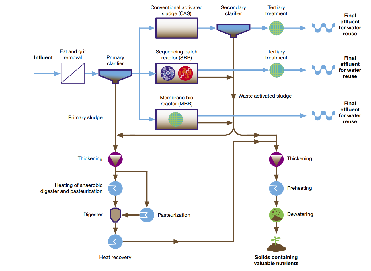
37 wastewater treatment process diagram
This article throws light upon the four processes of waste water treatment. The four processes are: (1) Preliminary Treatment (2) Primary Treatment (3) Secondary or Biological Treatment and (4) Tertiary or Advanced Treatment. 1. Preliminary Treatment: . As already stated, preliminary treatment involves the removal of floating materials (leaves, papers, rags) and settleable inorganic solids ... The wastewater treatment plant includes an oil separation tank, an equalization tank, two activated sludge tanks, three contact aeration tanks, a settling tank ...
As wastewater enters the sedimentation tanks (settling tanks) of the primary treatment phase, the flow of water is slowed. This permits heavier solids to settle ...

Wastewater treatment process diagram
Wastewater Treatment Plant Process Flowchart. Raw. Influent. F lo w to. /fro m. E q. T a n k. Mixed Liquor. T. Parshall. Flumes. Blowers. R. A. S. Download scientific diagram | Process flow diagram of the petroleum refinery wastewater treatment plant (PRWWTP) containing conventional activated sludge ... WASTEWATER TREATMENT PROCESS Wastewater Treatment Total water treatment system, employed to treat the waste/effluent water from industry. ( Image: courtesy of wikipedia) Pre-Treatment Removal of insoluble particles from reaching treatment zone, which may hinder treatment operation. 1) Grit removal, 2) flow equalisation, 3) Fat and grease removal
Wastewater treatment process diagram. II. Chevron Wastewater Treatment ... In the process of generating a system modeling water use in a refinery, six units will ... A process flow diagram of an amine-sweetening unit is shown in Figure 6. 8 Figure 6. Amine-sweetening unitxiii Wastewater Treatment Safe Drinking Water Foundation. Existing Wwtp Flow Schematics And Layout City Of Reading Pennsylvania. A schematic of typical wastewater treatment plant scientific diagram representation waste water and pilot scale indicating the sampling amol s b points sewage flow 2 process. Wiring. The ORCA Sonar Bed Level System is one of our most popular products used throughout the water and wastewater industry. The ORCA Sonar Bed Level System will measure up to two density interfaces simultaneously. Typically these are bed levels / RAS blanket and floc / fluff layers. The sonar produces a high power concentrated beam, and provides ... In waste water purification microbial nitrogen rich carbon poor (or low C/N ratio) environments of denitrification process may serve as key to clean water. When C/N ratio is high causing short circuiting nitrogen cycle the objective of waste water treatment is defeated. 2. Treatment of waste and waste water from food industries:
Download scientific diagram | Schematic diagram of domestic wastewater treatment process illustrating different stages of water and sludge treatment along ... sedimentation preceding secondary treatment or as a step in advanced wastewater treatment. Fine screens as a preliminary or primary treatment are more applicable to process or industrial wastes. TM 5-814-3 provides detailed descriptions of these units and design considerations. (b) Comminution. A comminutor acts as both a cutter and a screen. Wastewater, also known as raw sewage include but is not limited to water from the bathroom, toilets kitchen and other industrial wastes. Wastewater treatment is a process of removing micro-organisms, contaminants and any other pollutants from the wastewater.. Everyday wastewater from our homes, schools toilets, businesses and even factories goes down and flows into the City's sewer system. plants. Sewers collect the wastewater from homes, businesses, and many industries, and deliver it to plants for treatment. Most treatment plants were built to clean wastewater for discharge into streams or other receiving waters, or for reuse. Years ago, when sewage was dumped into waterways, a natural process of purification began.
Figure 1. Simple flow diagram of sewage treatment. ... Sewage sludge is obtained from wastewater treatment in sewage treatment plants. The sludge consists of two ... The process flow for a typical wastewater treatment plant (WWTP) is shown in Figure 1. The solid red arrows indicate the process flow of the wastewater ... MODIFIED LUDZACK ETTINGER NITROGEN REMOVAL PROCESS EXAMPLE GIVEN: Q + Q RAS NO,aer Q Wastewater average flow rate, Q = 40,000 m3/d Influent concentration Soluble COD (S SO) 150 mg/l Particulate COD (X SO) 115 mg/l Soluble ammonia-N (S NHO) 25 mg-l N Soluble organic N (S NSO) 6.5 mg/l Particulate organic N (X NSO) 8.5 mg/l Parameters Ö H 6 d-1 Ö A WASTEWATER TREATMENT PROCESS Wastewater Treatment Total water treatment system, employed to treat the waste/effluent water from industry. ( Image: courtesy of wikipedia) Pre-Treatment Removal of insoluble particles from reaching treatment zone, which may hinder treatment operation. 1) Grit removal, 2) flow equalisation, 3) Fat and grease removal
Download scientific diagram | Process flow diagram of the petroleum refinery wastewater treatment plant (PRWWTP) containing conventional activated sludge ...
Wastewater Treatment Plant Process Flowchart. Raw. Influent. F lo w to. /fro m. E q. T a n k. Mixed Liquor. T. Parshall. Flumes. Blowers. R. A. S.


0 Response to "37 wastewater treatment process diagram"
Post a Comment