37 shop vac switch wiring diagram
Rocker Switch & Wiring Diagram; Wiring Diagram; Hydraulic Bi-Directional Manual Lift 2011 & Older. Hydraulic Manual Lift 2006 - 2011; Wiring Diagram 2006 & Older; Wiring Diagram 2007 - 2011; 48" & 60" Hydraulic Dozer 2012+ Hydraulic Dozer Assy; Joystick & Wiring Diagram; Wiring Diagram; 48" & 60" Hydraulic Dozer 2008/2011. Hydraulic Dozer Assy ... 07.08.2013 · The solution is to get a relay (an electrically operated switch) with a 120 VAC coil and normally closed (n.c.) contacts that are rated at least 10 amp, DC. The figure below shows how to wire it. Connect the relay coil to the inverter output. Then disconnect the hot supply line from the converter and reconnect it through the n.c. relay contacts. Now, when the inverter is turned on or off, the ...
I have wiring diagram off of motor tag an changed wires around incase that was the problem. No luck. all 4 wires coming out of motor are black so color coated diagram does me no good at this point. IT is a Wagner alternating current motor, type-RA, frame-225, model-B1211 M 295, 3 Hp, 1750 RPM, 1 phase, 60 cycles. is the information on the tag. any info would be helpful.

Shop vac switch wiring diagram
Requires 24 VAC power (“C” wire). C-Wire Power Adapter included to provide power if needed ; Does not work with electric baseboard heat (120V - 240V) Does not work with millivolt systems; Does not support input (S terminals) for indoor and outdoor sensors; Does not support relay (U terminals) for ventilation; Is compatible with Android or iOS smartphone, tablet, or device; I want to check ... I spoke to my contact at Bulldog and he informed me that the Bulldog Powered Drive Kit part # BD1824200100 that you referenced can only be installed on the driver side of the trailer due to how the gears of the jack setup. To see how it all wires up check out the wiring diagram I attached that I took from the installation instructions for this kit. VAC 120 VAC "Neutral" Toggle switch Indicator light Limit switch Solenoid coil Temperature switch Fuse As you can see, the symbolism in ladder diagrams is not always the same as in electrical schematic diagrams. While some symbols are identical (the toggle switch, for instance), other symbols are not (the solenoid coil, for instance). Re-draw this ladder diagram as a schematic diagram ...
Shop vac switch wiring diagram. Just follow the same wiring setup for the first switch with the second switch. - THIS IS FOR NO ONLY! One side of each switch goes to Gnd - the other to the appropriate port on the X Controller - looks like pins 10,9, & 7 on your diagram. There is 5V already present on these lines. These are pulled up internally on the microcontroller. So they ... You can observe the connections of the KEY-SWITCH [10] in case you prefer a manual key start. You are required to use pilot relays to drive solenoids to start and stop the engine [7]. In the following diagram, the outputs of the controller are positive. You are required to connect to battery minus the other side of each relay coil. The use of flywell diodes is highly recommended. The inputs ... View and Download Polaris Magnum 2x4 service manual online. Polaris ATV And Light Utility Vehicle Service Manual. Magnum 2x4 offroad vehicle pdf manual download. Also for: Trail blazer, Scrambler, 1996 magnum 2x4, 1996 trail blazer, 1996 scrambler, 1996 sportsman 4x4, 1996 magnum 4x4,... Field Wiring. Above is the field or power wiring diagram. If you look closely you will see all the basic elements from the very simple static phase converter diagram shown earlier. Contactor C1 has replaced the drum switch, and Contactor C2 has replaced the momentary pushbutton for connecting the starting capacitor between L2 and L3.
VAC 120 VAC "Neutral" Toggle switch Indicator light Limit switch Solenoid coil Temperature switch Fuse As you can see, the symbolism in ladder diagrams is not always the same as in electrical schematic diagrams. While some symbols are identical (the toggle switch, for instance), other symbols are not (the solenoid coil, for instance). Re-draw this ladder diagram as a schematic diagram ... I spoke to my contact at Bulldog and he informed me that the Bulldog Powered Drive Kit part # BD1824200100 that you referenced can only be installed on the driver side of the trailer due to how the gears of the jack setup. To see how it all wires up check out the wiring diagram I attached that I took from the installation instructions for this kit. Requires 24 VAC power (“C” wire). C-Wire Power Adapter included to provide power if needed ; Does not work with electric baseboard heat (120V - 240V) Does not work with millivolt systems; Does not support input (S terminals) for indoor and outdoor sensors; Does not support relay (U terminals) for ventilation; Is compatible with Android or iOS smartphone, tablet, or device; I want to check ...
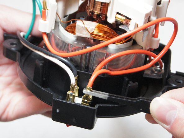


![[TD_0601] Ridgid Shop Vac Wiring Diagram On Shop Vac ...](https://static-cdn.imageservice.cloud/6756079/shop-vac-wire-diagram-everything-wiring-diagram.jpg)
![[DIAGRAM] Wiring Diagram For Shop Vac FULL Version HD ...](https://www.ereplacementparts.com/images/shop-vac/16LT550A_WW_1.gif)
![[KA_3162] Shop Vac Motor Diagram Motor Repalcement Parts ...](https://static-cdn.imageservice.cloud/965135/dyson-vacuum-parts-vacuum-direct.jpg)
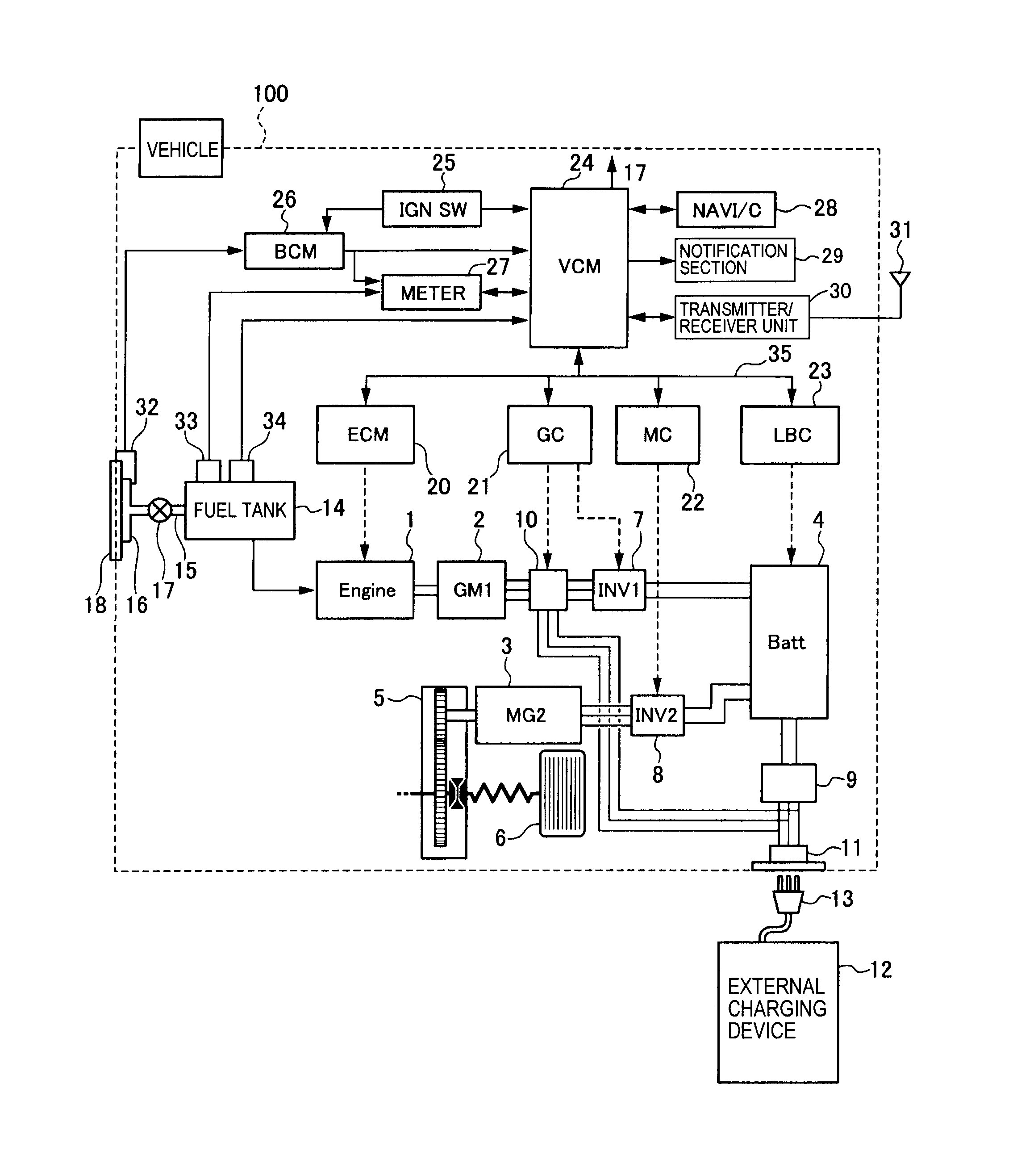

![[ME_6944] Ridgid Shop Vac Wiring Diagram On Shop Vac ...](https://static-resources.imageservice.cloud/6756076/parts-6-gallon-wetdry-vac-ridgid-store.jpg)
![[KA_3162] Shop Vac Motor Diagram Motor Repalcement Parts ...](https://static-resources.imageservice.cloud/866544/parts-lists-shop-vac.jpg)


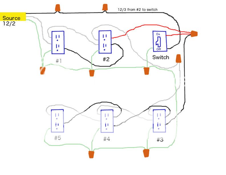
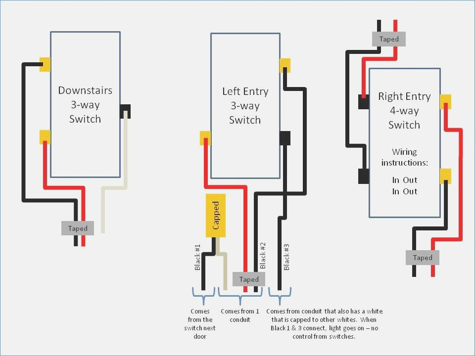

![[ME_6944] Ridgid Shop Vac Wiring Diagram On Shop Vac ...](https://static-resources.imageservice.cloud/6756085/parts-4-gallon-portable-wetdry-vac-ridgid-store.jpg)
![[TD_0601] Ridgid Shop Vac Wiring Diagram On Shop Vac ...](https://static-cdn.imageservice.cloud/6756064/parts-16-gallon-stainless-steel-wetdry-vac-with-cart.jpg)



![[KA_3162] Shop Vac Motor Diagram Motor Repalcement Parts ...](https://static-resources.imageservice.cloud/6799010/shop-vac-switch-wiring-diagram-shop-vac-cabinet-shop-vac-hose.jpg)


0 Response to "37 shop vac switch wiring diagram"
Post a Comment