37 fe cr phase diagram
The phase diagram for the common end members of the olivine solid solution series shows that pure forsterite melts at 1890 o C and pure fayalite melts at 1205 o C. Thus, the olivines are sometimes seen be be zoned from Mg-rich cores to more Fe-rich rims, although such zoning is usually limited to 5 to 10% difference between the cores and the rims. Click on a system to display the phase diagram. (NH4)2SO4-H2O FTfrtz (NH4)2SO4-H2O_with_gas FTfrtz ... C-Cr-Fe_1000K SGTE 2014: C-Cr-Fe_500K SGTE 2014:
PDF | Photocatalysis has been extensively studied due to its potential ability to avoid the excessive use of chemical reagents and reduce the energy... | Find, read and cite all the research you ...
Fe cr phase diagram
38 which part of the constitution is the basis for this diagram Written By Tim C. Meyers. Monday, November 22, 2021 Add Comment Edit. In this post, I want to go over what I think is the most charitable interpretation of what I think is one of Nāgārjuna's most interesting arguments. The engine may stall intermittently. You may notice poor engine performance including irregular acceleration, misfiring, hard starting, or surging. On some car models, a failed CMP sensor will prevent the ignition from making a spark, so that the engine won't start at all. pinterest-pin-it. Camshaft position sensor. On 26 May 2019, a C210 registered VH-SUX and operated by Thomson Aviation, departed Mount Isa Airport for a geological survey flight. During the flight, the aircraft's right wing separated, resulting in a rapid loss of control and collision with terrain. The pilot and observer were fatally injured and the aircraft was destroyed.
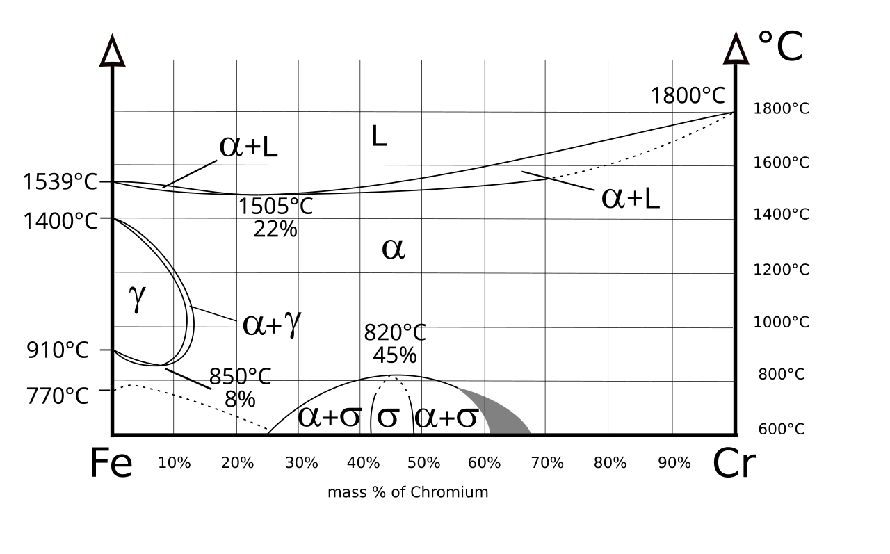
Fe cr phase diagram. Cr Si Mn W Mo Review Fe-C phase diagram • 2 important points-Eutectoid (B): γ⇒α+Fe 3C-Eutectic (A): L ⇒γ+Fe 3C Fe 3 C (cementite) 1600 1400 1200 1000 800 600 400 0 12 3 4 5 66.7 L γ (austenite) γ+L γ+Fe 3C α+Fe 3C α + γ L+Fe 3C δ (Fe) C o, wt% C 1148°C T(°C) α 727°C = Teutectoid A R S 4.30 Result: Pearlite = alternating ... (1) In 1907, Treitschke and Tammann found that the 𝜎 phase in the Fe-Cr binary system was an intermetallic compound of 30 wt.% Cr~50 wt.% Cr . (2) In 1927, Bain and Griffiths observed the successful 𝜎 phase in the Fe-Cr-Ni ternary system. Calais da Silva FE, Bono AV, Whelan P, Brausi M, et al. Intermittent androgen deprivation for locally advanced and metastatic prostate cancer: results from a randomised phase 3 study of the South ... The potential reproduces, for example, the lattice parameter(s), formation energies and elastic properties of the principal Fe and Cr carbides (Fe3C, Fe5C2, Fe7C3, Cr3C2, Cr7C3, Cr23C6), the Fe–Cr mixing energy curve, formation energies of simple C point defects in Fe and Cr, and the martensite lattice anisotropy, with fair to excellent ...
1. Locate composition and temperature in diagram 2. In two phase region draw the tie line or isotherm 3. Fraction of a phase is determined by taking the length of the tie line to the phase boundary for the other phase, and dividing by the total length of tie line The lever rule is a mechanical analogy to the mass balance calculation. Despite the phase change from 14M to 10M, the domain structure exhibited very similar patterns, indicating that the orientation of the c-axis was constant and there was no a/c twinning in either the 14M or 10M phase. This suggests very good compatibility between the 10M and 14M martensite phases. Nov 02, 2021 · This is similar to the phase equilibria observed in Fe-rich Al–Fe-[Co,Ni] ternary systems [, , ], whereby elements in the pairs Al and Ti; Co and Ni; and Fe and Cr tend to play similar roles in the phase equilibria. The spinodal-like microstructure observed at the dendrite edges and within interdendritic regions is a result of high ... A phase II study of paclitaxel plus carboplatin as first-line chemotherapy for women with metastatic breast carcinoma. Cancer . 2000 Jan 1. 88(1):124-31. [Medline] .
A free-body diagram for a left segment of the beam extending a distance x within region BC is shown in Fig. 6-4c. As always,V and M are shown acting in the positive sense. Hence, (3) (4) The shear diagram represents a plot of Eqs. 1 and 3, and the moment diagram represents a plot of Eqs. 2 and 4, Fig. 6-4d.These equations can 金属やセラミックスの状態図、エンリンガム図などの情報を提供しています。 一部、不確かなものもありますので、自己 ... An Ellingham diagram is a graph showing the temperature dependence of the stability of compounds. This analysis is usually used to evaluate the ease of reduction of metal oxides and sulfides.These diagrams were first constructed by Harold Ellingham in 1944. In metallurgy, the Ellingham diagram is used to predict the equilibrium temperature between a metal, its oxide, and oxygen — and by ... SGTE - SGTE 2017 Alloy Phase Diagrams (1176) Click on a system to display the phase diagram.
D Nb Info
Phase Diagram Resources from ASM International. Alloy phase diagrams and crystal structure data are used by metallurgists, materials engineers, and materials scientists to develop new alloys for specific applications; fabricate these alloys into useful configurations; design and control heat treatment procedures for alloys that will produce the required mechanical, physical, and chemical ...
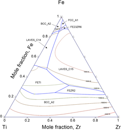
Thermodynamic Description Of Hydrogen Storage Materials Cr Ti Zr And Fe Ti Zr Journal Of Materials Research Cambridge Core
Principles of Measurement Systems We work with leading authors to develop the strongest educational materials in engineering, bringing cutting-edge thinking and best learning practice to a global market.
File Phase Diagram Of Fe Cr Svg Wikimedia Commons
Noticias económicas de última hora, información de mercados, opinión y mucho más, en el portal del diario líder de información de mercados, economía y política en español

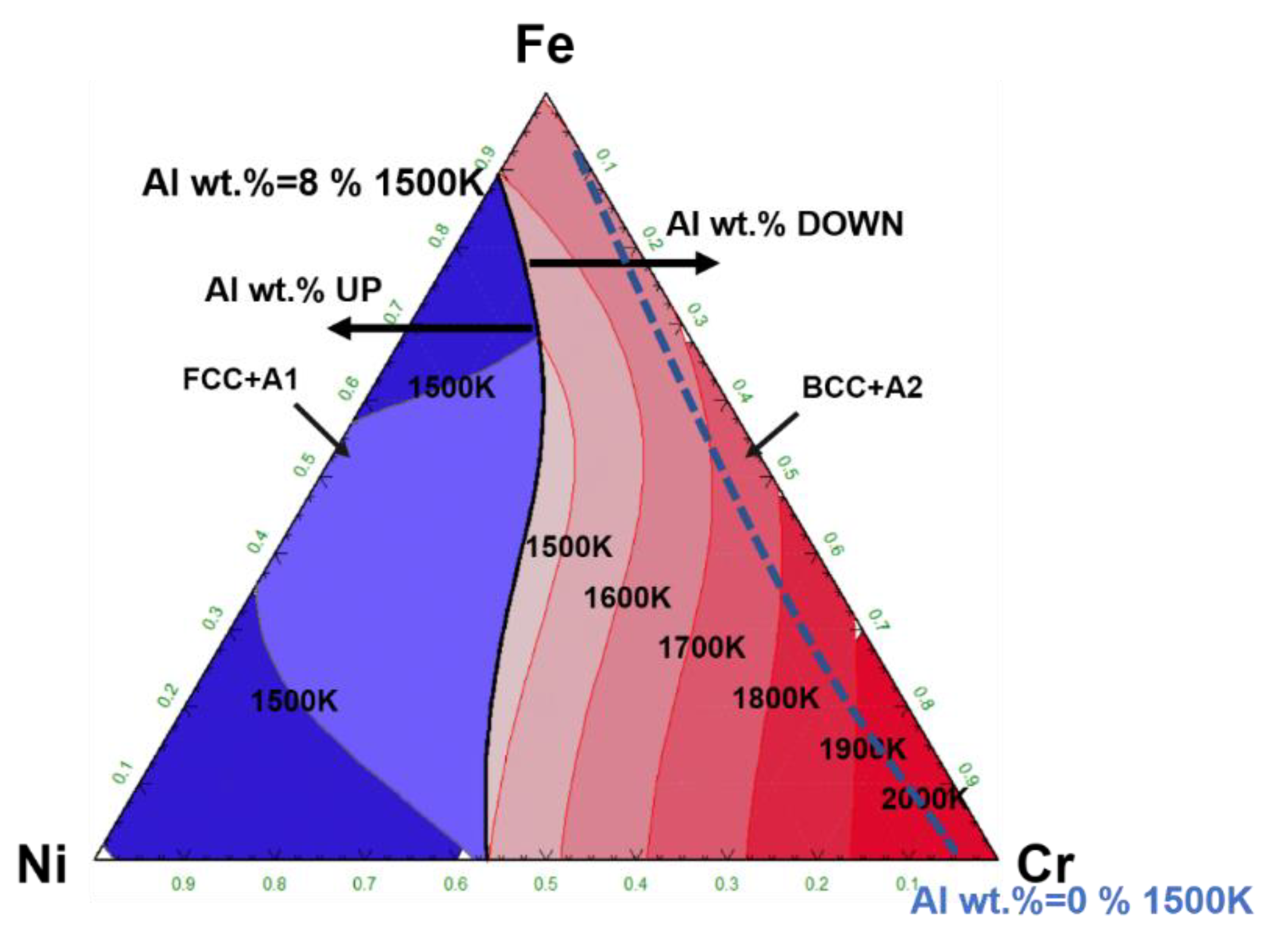
Fig 3 Ni Cr Fe Ternary Equilibrium Phase Diagram At 800 C And Ni Cr Fe Alloys And The Target Alloys Blue Colored Area
Browse up-to-the-minute automotive news and analysis, including expert reviews of the latest cars on the market, at Cars.com.
Diva Portal Org
Aug 01, 2013 · In the present Co–Cr–Fe–Mn–Ni alloys, no phase separation was observed, even though they were furnace-cooled from homogenization temperatures. This can be understood based on two reasons. First, in HEA, the high mixing entropy enhances the mutual solubility between elements and the stability of solution phases [76] .
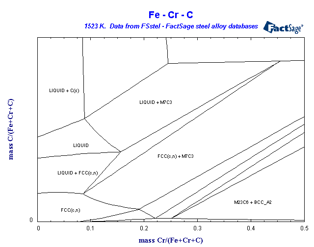
Fsstel Factsage Steel Alloy Phase Diagrams
Silicon is a chemical element with the symbol Si and atomic number 14. It is a hard, brittle crystalline solid with a blue-grey metallic lustre, and is a tetravalent metalloid and semiconductor.It is a member of group 14 in the periodic table: carbon is above it; and germanium, tin, lead, and flerovium are below it. It is relatively unreactive. Because of its high chemical affinity for oxygen ...

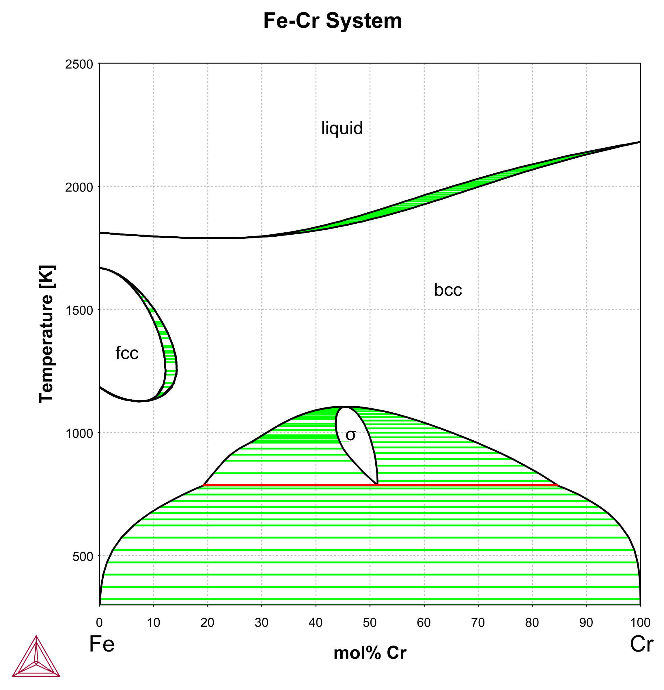
File Fe Cr Phase Diagram Svg Wikipedia
Bentonite sample enriched in organic matters (oil shale) was functionalized with −SO3H sulfonated carbonaceous bentonite (S-CB) by sulfonation process as a low-cost and effective acidic catalyst for the transesterification spent sunflower oil (SFO). The sulfonation effect was followed by several analytic techniques including X-ray diffraction, Fourier transform infrared, and scanning ...

Fe Cr Ni Phasediagram Sections Youtube
Thus, the content of Cr (12.72 at. %) in the second phase is much lower than Fe (38.63 at. %). According to the Cr-Zr binary phase diagram , Cr mainly exists in the form of α-ZrCr 2 in Zr when the temperature is below 836 °C (higher than the bonding temperature). The maximum atomic ratio of Fe in the second phase is 42.86 at.

Physical Metallurgy 19 Th Lecture Ppt Video Online Download
SpMCBN - Spencer Group M-C-N-B-Si Alloy Phase Diagrams (837) Click on a system to display the phase diagram.
Fe Cr Japan Atomic Energy Agency
Iron (/ ˈ aɪ ər n /) is a chemical element with symbol Fe (from Latin: ferrum) and atomic number 26. It is a metal that belongs to the first transition series and group 8 of the periodic table.It is, by mass, the most common element on Earth, right in front of oxygen (32.1% and 30.1%, respectively), forming much of Earth's outer and inner core.It is the fourth most common element in the ...
Metals Free Full Text Study On S Phase In Fe Al Cr Alloys Html
Heterostructures of correlated electronic systems offer versatile platforms for various types of quantum phases and their transitions. A common wisdom states that the proximity coupling between constituent layers plays a secondary role, because it is much weaker than the intralayer interactions. In this work, we present a counterexample of the belief.

Figure 4 Precipitation Of Phase Using General Diffusion Equation With Comparison To Vitek Diffusion Model In Dissimilar Stainless Steels
The present work examines this critically in Fe-Cr system using atom probe tomography (APT) and small angle neutron scattering (SANS), and establishes the framework to distinguish the two different modes of alpha-prime phase separation in thermally aged Fe-35 at.% Cr and Fe-20 at.% Cr alloys.
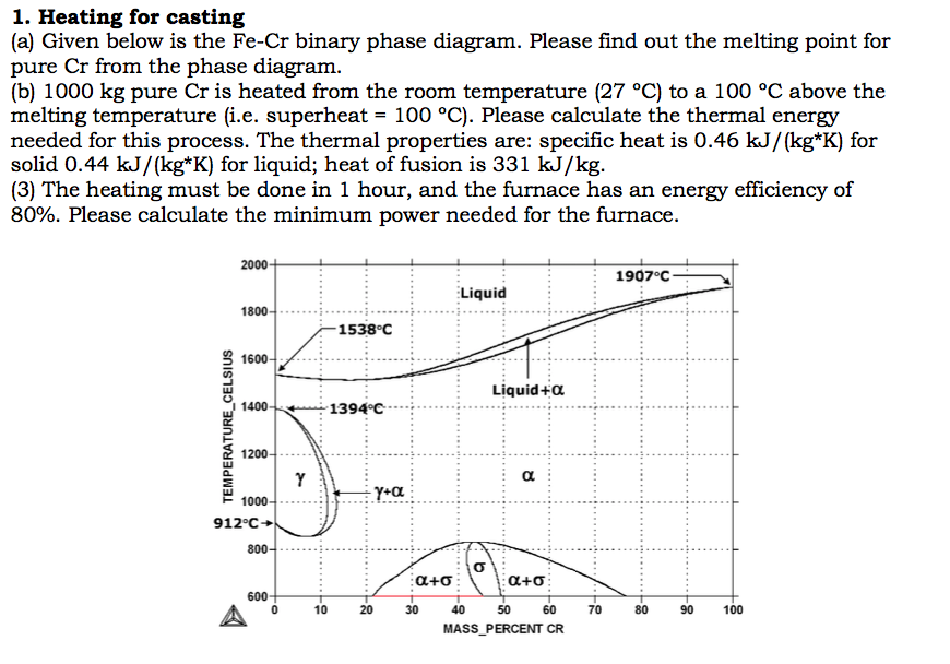
Solved A Given Below Is The Fe Cr Binary Phase Diagram Chegg Com
Nov 15, 2021 · Rv Water Tank Wiring Diagram - wiring diagram is a simplified all right pictorial representation of an electrical circuit. to inquire further, I suggest you contact either your dealer to have them attempt obtaining them for you or contact Heartland Customer Service to have a chat with them on the matter (877-262-8032). I had to make the switch panel hole larger to accommodate ...
Arxiv Org
Metal-organic frameworks (MOFs) are promising materials for the photocatalytic H2 evolution reaction (HER) from water. To find the optimal MOF for a photocatalytic HER, one has to consider many different factors. For example, studies have emphasized the importance of light absorption capability, optical band gap, and band alignment. However, most of these studies have been carried out on ...
.png)
Fe Cr C 1000 K Japan Atomic Energy Agency
金属やセラミックスの状態図、エンリンガム図などの情報を提供しています。 一部、不確かなものもありますので、自己 ...

Local Thermal Processing Effects In The Morphological Transformations Compression
Orbital diagrams are ways to assign electrons in an atom or ion. Each atomic orbital is represented by a line or a box and electrons in the orbitals are represented by half arrows. Orbital diagram for cr3+. The electronic configuration of Cr having atomic number of 24 is 1s 2 2s 2 2p 6 3s 2 3p 6 4s 1 3d 5 which is half-filled d-orbital..
Cmphys Lab Com
In atomic physics and quantum chemistry, the electron configuration is the distribution of electrons of an atom or molecule (or other physical structure) in atomic or molecular orbitals. [1] For example, the electron configuration of the neon atom is 1s 2 2s 2 2p 6, meaning that the 1s, 2s and 2p subshells are occupied by 2, 2 and 6 electrons respectively.
Avesis Ktu Edu Tr
A new ternary phase in the system CaO-Al 2 O 3 -Cr 2 O 3: Crystal structure and thermal expansion of CaAl 2 Cr 2 O 7 Volker Kahlenberg , Johan P.R. de Villiers , Dirk Odendaal , Hannes Krüger , Shengqiang Song , Mithun Nath ,
Ferro Chrome Ispatguru
In particular, if a Cr atom is displaced, the FM-AFM sign change when the I-Cr-I bond angle approaches 90$^\circ$. The obtained spin-lattice coupling constants, along with the microscopic orbital analysis can act as a guiding principle for further studies of the thermodynamic properties and combined magnon-phonon excitations in two-dimensional ...

Scielo Brasil Phase Transformations In An Aisi 410s Stainless Steel Observed In Directional And Laser Induced Cooling Regimes Phase Transformations In An Aisi 410s Stainless Steel Observed In Directional And Laser Induced
The phases in the Al 63 Cu 25 Fe 12 alloy primarily consisted of the I-phase, β-Al 0.5 Fe 0.5 phase (β-phase) and θ-Al 2 Cu 3 phase (θ-phase). When Ce was added, the most prominent peaks observed in the image of the Al-Cu-Fe-Ce (x = 0.1, 0.5, 1 and 2 at%) alloys corresponded to the I-phase, β-phase and Al 13 Ce 2 Cu 13 phase.

Phase Diagram Of The Ag2se As2se3 System And Crystal Structure Of The Agas3se5 Compound
Potentially toxic element pollution in wastewater, especially chromium (Cr), has aroused much concern worldwide. Commonly, Cr exists in aqueous phase as two major oxidation valence states, i.e., the hexavalent (Cr(VI)) and trivalent Cr (Cr(III)) states (Zhou et al. 2016).Oxyanionic Cr(VI) is more poisonous and can threaten to function of ecosystem and human health.
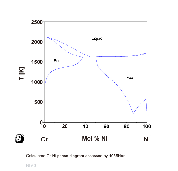
Cr Ni Nims
Thermodynamics, microstructures, and plasticity [proceedings of the NATO Advanced Study Institute, held in Frejus, France, September 2-13, 2002]

File Fe Cr Ni Solidus Phase Diagram Svg Wikimedia Commons
On 26 May 2019, a C210 registered VH-SUX and operated by Thomson Aviation, departed Mount Isa Airport for a geological survey flight. During the flight, the aircraft's right wing separated, resulting in a rapid loss of control and collision with terrain. The pilot and observer were fatally injured and the aircraft was destroyed.
Tandfonline Com
The engine may stall intermittently. You may notice poor engine performance including irregular acceleration, misfiring, hard starting, or surging. On some car models, a failed CMP sensor will prevent the ignition from making a spark, so that the engine won't start at all. pinterest-pin-it. Camshaft position sensor.

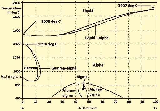
Fe Cr Binary Phase Diagram Adapted From Massalski See Ref 7 Download Scientific Diagram
38 which part of the constitution is the basis for this diagram Written By Tim C. Meyers. Monday, November 22, 2021 Add Comment Edit. In this post, I want to go over what I think is the most charitable interpretation of what I think is one of Nāgārjuna's most interesting arguments.

A Thermodynamic Evaluation Of The Fe Cr C System Sciencedirect

Binary Iron Chromium Equilibrium Phase Diagram 15 18 Download Scientific Diagram

Ni Laboratory

Ferritic Stainless Steel Wikiwand

Journal Of Materials

Phase Diagrams And Elastic Properties Of The Fe Cr Al Alloys A First Principles Based Study Sciencedirect

Ferritic Stainless Steel Wikipedia
H2020 M4f Eu
Tel Archives Ouvertes Fr
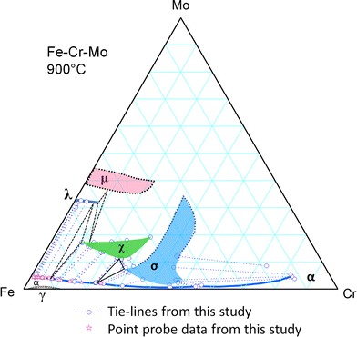
Determination Of The Fe Cr Mo Phase Diagram At Intermediate Temperatures Using Dual Anneal Diffusion Multiples Springerlink

Austenitic Steels Total Materia Article
Fe Cr Binary Phase Diagram Adapted From Massalski See Ref 7 Download Scientific Diagram
0 Response to "37 fe cr phase diagram"
Post a Comment